Read Sharp AR-F14 (serv.man9) Service Manual online
AR-F14/PN1 TROUBLE SHOOTING 9-6
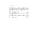
(3) F1-34, Punch Motor Fault
(4) F1-35, Punch Sensor (horizontal registration) Fault
(5) F1-38, Puncher Back-UP Memory Fault
(6) F1-39, Punch sensor (waste full) Fault
(7) F1-40, Puncher Unit Power Supply Fault
C. Interface transport section
(1) F1-53 display ON, interface transport unit connection trouble
Cause/Trouble section
Procedure
Check
Result
Remedy
Punch motor home position sensor
(XXXX)
(XXXX)
1
Check the punch home position sensor. Is the sensor normal?
NO
Replace the sensor.
Punch motor clock sensor (PE)
2
Check the punch motor clock sensor. Is the sensor normal?
NO
Replace the sensor.
Wiring
3
Is the wiring between the finisher controller PCB and the sensor
normal?
normal?
NO
Correct the wiring.
Punch mechanism,
Punch motor (FPNM)
Punch motor (FPNM)
4
Is there a fault in the punch mechanism?
YES
Correct the punch
mechanism.
mechanism.
NO
Replace the punch
motor.
motor.
Punch controller PCB,
Finisher controller PCB
Finisher controller PCB
5
Try replacing the punch controller PCB. Is the problem corrected?
YES
End.
NO
Replace the fisher
controller PCB.
controller PCB.
Cause/Trouble section
Procedure
Check
Result
Remedy
Horizontal registration sensor
(photosensor PCB/LED PCB)
(photosensor PCB/LED PCB)
1
Check the horizontal registration sensor. Is the sensor normal?
NO
Replace the sensor.
Wiring
2
Is the wiring between the punch controller PCB and the horizontal
registration sensor normal?
registration sensor normal?
NO
Correct the wiring.
Punch controller PCB,
Finisher controller PCB
Finisher controller PCB
3
Try replacing the punch controller PCB. Is the problem correct?
YES
End.
NO
Replace the finisher
controller PCB.
controller PCB.
Cause/Trouble section
Procedure
Check
Result
Remedy
EEP-ROM (IC1002)
1
Is the problem corrected by initializing the EEP-ROM on the
punch controller PCB?
punch controller PCB?
YES
End.
Punch controller PCB
2
Turn off and the on the host machine. Is the problem corrected?
YES
End.
NO
Replace the punch
controller PCB.
controller PCB.
Cause/Trouble section
Procedure
Check
Result
Remedy
Waste full Sensor
(waste full photosensor PCB/
waste full LED PCB)
(waste full photosensor PCB/
waste full LED PCB)
1
Check the waste full sensor. Is the sensor normal?
NO
Replace the sensor.
Wiring
2
Is the wiring between the punch controller PCB and the waste full
sensor normal?
sensor normal?
NO
Correct the wiring.
Punch controller PCB,
Finisher controller PCB
Finisher controller PCB
3
Try replacing the punch controller PCB. Is the problem corrected?
YES
End.
NO
Replace the finisher
controller PCB.
controller PCB.
Cause/Trouble section
Procedure
Check
Result
Remedy
Finisher controller PCB,
Host machine DC controller PCB
Host machine DC controller PCB
1
Turn off and then off the host machine. Is the problem corrected?
YES
End.
Wiring
2
Is the wiring between the finisher controller PCB and the punch
controller PCB normal?
controller PCB normal?
NO
Correct the wiring.
Power supply
3
Measure the voltage between CN14-5 (+) and CN4-3 (-) on the
finisher controller PCB. Is it 24 VDC?
finisher controller PCB. Is it 24 VDC?
YES
Replace the punch
controller PCB.
controller PCB.
NO
Replace the finisher
controller PCB.
controller PCB.
Cause/
Trouble section
Procedure
Check
Result
Process
Wiring
1
Is the connector connected between the finisher and the interface transport unit?
NO
Connect the connector.
Wiring
2
Is the trouble canceled when harness of the interface transport section is replaced?
YES
END
NO
Replace the finisher
control PWB.
control PWB.
[09]TROUBLESHOOTING.fm 6 ページ 2004年4月19日 月曜日 午後1時42分

