Read Sharp AR-F14 (serv.man3) Service Manual online
AR-F14/PN1 UNPACKING AND INSTALLATION 3-1
[3] UNPACKING AND INSTALLATION
1.AR-F14
<Before installation>
•For installation of AR-F14, an optional stand (small stand or large stand)
must have been installed.
•When adjusting the height of the finisher, be sure to perform step15)
with the finisher placed on the packing box.
•For improvement of workabillity, part of the description in this manual
may be modified without prior notice. In this case, refer to the service
manual.
manual.
Turn off the main switch of the copier and then remove the power plug
from the outlet.
from the outlet.
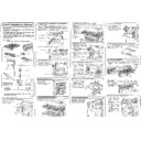
1) Remove the exit tray cover.
•If the copier is equipped with an exit tray cover:
•If the copier is equipped with an exit tray cover:
Remove the screw and then remove the exit tray cover as shown in the
illustration.
2) Remove the internal cabinet and the paper holder arm from the
copier.
<1>Pull the lock lever to the left and pull out the rail dummy cover to
the front.
(If the second exit tray is provided, remove it together with the rail
dummy cover.)
<2>Unlatch the pawls of the exit dummy cover and remove the exit
dummy cover.
<3>Remove the paper holder arm from the exit dummy cover.
<4>Remove the screw and then remove the rear exit cover.
3) Remove the rear cabinet.
<1>Remove the screw and then remove the maintenance cover.
<2>Remove the four screws and then remove the rear cabinet.
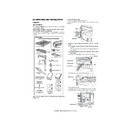
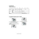
Punch position label:
2 sheets
Stapling position label:
2 sheets
Saddle finisher
instruction manual:
1 copy
[03]UNPACKINGANDINSTALLATION.fm 1 ページ 2004年4月27日 火曜日 午後7時4分
AR-F14/PN1 UNPACKING AND INSTALLATION 3-2
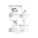
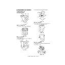
4) Remove the right cabinet.
<1>Open the bypass tray.
<2>Open the right door.
<3>Remove the two screws and then remove the right cabinet.
5) Remove the copier second exit unit.
<1>Remove the connector of the copier second exit unit from the
copier.
<2>Remove the four screws and then remove the copier second exit
unit.
6) Attach the supplied F14 second exit unit.
<1>Arrange the connector harness of the supplied F14 second exit
unit as shown in the illustration.
<2>Attach the F14 second exit unit to the copier and secure it with
the four screws.
At this time, take care so that the harness is not caught between
the copier and the second exit unit.
<3>Connect the connector to the copier.
7) Attach the rear cabinet.
<1>Reattach the rear cabinet to its original position and secure it
with the four screws.
<2>Reattach the maintenance cover to its original position and
secure it with the screw.
<3>Reattach the right cabinet that has been removed in step4) to its
original position and secure it with the two screws.
<4>Close the right door and the bypass tray.
8) Attach the docking mounting angles.
<1>Cut out the two cut-out portions on the left cabinet of the copier
using nippers or the like.
(Be careful about the orientation of the nippers so that the cross
(Be careful about the orientation of the nippers so that the cross
section is flat.)
<2>Secure the docking mounting angle F and docking mounting
angle R with two screws A (M4 x 10) each.
(F/R is indicated with marking.)
9) Remove the covers from the docking unit.
<1>Remove the screw and slide the top cover in the direction of the
arrow to remove it.
<2>Remove the two screws and then remove the front cover.
<3>Remove the four screws and then remove the left cover.
[03]UNPACKINGANDINSTALLATION.fm 2 ページ 2004年4月27日 火曜日 午後7時4分
AR-F14/PN1 UNPACKING AND INSTALLATION 3-3
10) Attach the docking unit.
Insert docking mounting angel F and docking mounting angel R that
have been attached to the copier, into the holes of the docking unit.
11) Secure the docking unit.
<1>Use two screws A (M4 x 10) to secure the unit to the copier.
<2>Then use the screw that has been remove in step2) to secure the
docking unit.
12) Attach the paper holder arm to the transport unit.
Attach the paper holder arm that has been removed in step2) to the
lower part of the transport unit.
13) Attach the transport unit.
<1>Place the rail of the transport unit on the guide of the copier and
gently push it in.
<2>Connect the connector of the docking unit and then push the
transport unit in until it stops.
<3>Open the cover of the transport unit.
<4>Secure the unit with two screws A (M4 x 10).
<5>Close the cover of the transport unit.
<5>Close the cover of the transport unit.
14) Attach the covers of the docking unit.
<1>Reattach the left cover to its original position and secure it with
the four screws.
<2>Secure the front cover with the two screws.
<3>Secure the front cover to the docking unit using screw C from
<3>Secure the front cover to the docking unit using screw C from
above the front cover.
<4>Slide the upper cover to attach as shown in the illustration and
secure it with the screw.
[03]UNPACKINGANDINSTALLATION.fm 3 ページ 2004年4月27日 火曜日 午後7時4分
AR-F14/PN1 UNPACKING AND INSTALLATION 3-4
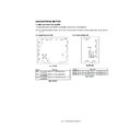
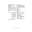
•If the copier is equipped with a small stand and three paper drawers,
proceed to step16).
•If the copier is equipped with a large stand and two paper drawers or a
small stand and four paper drawers, you must change the height of the
finisher. In this case, be sure to perform step15) with the finisher placed
finisher. In this case, be sure to perform step15) with the finisher placed
on the packing box.
15) Change the height of the finisher
(if the copier is equipped with a large stand and two paper drawers or
a small stand and four paper drawers)
<1>Remove the screw and then remove the cover.
<1>Remove the screw and then remove the cover.
<2>Remove the four screws that secure the fittings of the front side
and rear side respectively and then remove the two fittings.
<3>Extend the finisher stand, reattach the two fittings that have been
removed in <2>, and secure them with four screws for each.
<4>Reattach the cover and secure it with the screw.
16) Connect the finisher to the stand / paper drawers.
<1>Remove the cover from the finisher stand.
<2>Insert the connecting plate into the connecting plate mounting
<2>Insert the connecting plate into the connecting plate mounting
section and attach it with two screws B.
<3>Reattach the cover to its original position.
<4>Attach the ground plate as shown in the illustration and secure it
with screw B.
17) Secure the connecting plate to the stand / paper drawers.
Secure the finisher connecting plate to the stand / paper drawers
with two screws B (M4 x 6).
[03]UNPACKINGANDINSTALLATION.fm 4 ページ 2004年4月27日 火曜日 午後7時4分

