Read Sharp AR-F14 (serv.man5) Service Manual online
AR-F14/PN1 DISASSEMBLY AND ASSEMBLY 5-1
[5] DISASSEMBLY AND ASSEMBLY
1. Finisher Saddle Unit
A. Externals and Controls
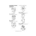
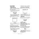
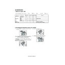
Fig.F03-101-01
(1)Removing the Delivery Tray
1) Remove the four screws [1], and detach the delivery tray [2].
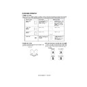
Fig.F03-101-02
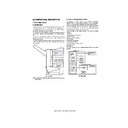
(2)Removing the Front Cover
1) Open the front door [1].
2) While picking the claw [2], detach the fold jam releasing dial [3].
3) Remove the two screws [4].
Fig.F03-101-03
4) Remove the three screws [5], and detach the front cover [6].
Fig.F03-101-04
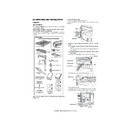
(3)Removing the Rear Cover
1) Remove the two screws [1] on the pickup side, and remove the screw
[2] on the delivery side; then, detach the rear cover [3].
Fig.F03-101-05
Fig.F03-101-06
(4)Removing the Upper Cover
1) Open the upper cover [1], and turn the cover band retainer [2] to the
left to remove it.
2) Remove the cover band [3].
Fig.F03-101-07
[1]
[2]
[3]
[4]
[5]
[6]
[7]
[2]
[1]
[1]
[4]
[4]
[3]
[2]
[6]
[5]
[5]
[3]
[1]
[3]
[2]
[2]
[1]
[3]
[05]DISASSEMBLYANDASSEMBLY.fm 1 ページ 2004年4月19日 月曜日 午後1時38分
AR-F14/PN1 DISASSEMBLY AND ASSEMBLY 5-2
3) Remove the screw [4], and detach the processing tray rear cover [5];
then, detach the upper.
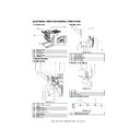
Fig.F03-101-08
(5)Removing the Processing Tray Upper Cover
1) Remove the front cover. (See 1.A.(2).)
2) Remove the rear cover. (See 1.A.(3).)
3) Remove the upper cover. (See 1.A.(4).)
4) Disconnect the connector [1], and remove the screw [2].
4) Disconnect the connector [1], and remove the screw [2].
Fig.F03-101-09
5) While lifting the processing tray upper cover [3], disconnect the
connector [4]; then, detach the processing tray upper cover [3].
Fig.F03-101-10
(6)Removing the Upper Right Cover Assembly
1) Remove the front cover. (See 1.A.(2).)
2) Remove the rear cover. (See 1.A.(3).)
3) Remove the two screws [1] at the front and the two screws [2] at the
3) Remove the two screws [1] at the front and the two screws [2] at the
rear; then, detach the upper right cover assembly [3].
Fig.F03-101-11
Fig.F03-101-12
(7)Removing the Saddle Guide
1) Remove the delivery tray. (See 1.A.(1).)
2) Remove the front cover. (See 1.A.(2).)
2) Remove the front cover. (See 1.A.(2).)
3) Remove the rear cover. (See 1.A.(3).)
4) Free the delivery tray support plate (front) [1] and the delivery tray
support plate (rear) [2] to the outside from the rail grooves.
5) Remove the four screws [3].
Fig.F03-101-13
6) Shift the side guide [4] lightly to the front, and free the engagement
of the paper surface detecting lever (rear) [5]; then, detach the side
guide [4].
Fig.F03-101-14
[6]
[4]
[5]
[2]
[1]
[3]
[4]
[3]
[1]
[2]
[3]
[1]
[2]
[3]
[3]
[3]
[3]
[5]
[4]
[05]DISASSEMBLYANDASSEMBLY.fm 2 ページ 2004年4月19日 月曜日 午後1時38分
AR-F14/PN1 DISASSEMBLY AND ASSEMBLY 5-3
NOTE: Be sure to mount the side guide after securely fitting the paper
surface detecting lever (rear) [5] in the groove of the paper
surface detecting lever (middle) [6].
After completion of mounting, push the paper surface detecting
lever several times to make sure that side guide is mounted
lever several times to make sure that side guide is mounted
securely.
Fig.F03-101-15
B.Feeding System
(1)Removing the Stapler Unit
1) Open the front door [1].
2) Slide out the stapler unit [3] while pressing the stopper [2].
2) Slide out the stapler unit [3] while pressing the stopper [2].
Fig.F03-102-01
NOTE: Do not remove the stapler stapler frame shaft. If removed, the
position where the staple driver (lower unit of the stapler) [4]
shoots stables will shift from the position where the staple
shoots stables will shift from the position where the staple
clincher (upper unit of the stapler) [5] receives staples.
Fig.F03-102-02
(2)Adjusting the Stapler Phase
When the gears or timing belt at the front of the stapler is replaced or
removed for some reason, the staple shooting timing of the (lower unit of
the stapler) does not match the staple bending timing of the staple
the stapler) does not match the staple bending timing of the staple
clincher (upper unit of the stapler). Adjust the stapler phase following the
procedure described below.
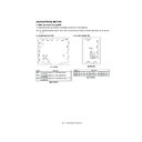
Fig.F03-102-03
1) Detach the gear cover [2] from the staple driver [1].
2) Remove the E-ring [3] to detach the side cover [5] of the staple
clincher [4].
Fig.F03-102-04
3) Remove the two E-rings [6] to remove the staple jam releasing gear
[7], timing belt [8], and relay gear 1 [9]. Remove the spacer and
spring at the back of the staple jam releasing gear.
spring at the back of the staple jam releasing gear.
4) Remove the screw [10] and spring [11] to remove the belt tensioner
[12].
Fig.F03-102-05
[6]
[5]
[5]
[6]
[1]
[3]
[2]
[5]
[4]
Timing belt
Gear
Gear
[2]
[5]
[3]
[4]
[1]
[8]
[10]
[12]
[6]
[7]
[11]
[9]
[05]DISASSEMBLYANDASSEMBLY.fm 3 ページ 2004年4月19日 月曜日 午後1時38分
AR-F14/PN1 DISASSEMBLY AND ASSEMBLY 5-4
5) Remove the timing belt [13].
6) Remove the E-ring [14] to remove the staple position check gear
6) Remove the E-ring [14] to remove the staple position check gear
[15].
Fig.F03-102-06
7) Turn the gear [16] to align the round hole in the staple driver gear
with the round hole [17] at the back.
Fig.F03-102-07
8) Insert a pin [18] with a diameter of approximately 2 mm
(use recommended) in the round hole to secure the gear.
Fig.F03-102-08
9) Turn the gear [19] to align the round hole in the staple clincher cam
with the round hole [20] at the back.
Fig.F03-102-09
10) Insert a pin [21] with a diameter of approximately 2 mm (use of a 2
mm Allen wrench is recommended) in the round hole to secure the
gear.
gear.
Fig.F03-102-10
11) With the gears and cam fixed, install the timing belt [22] on gears [23]
and [24].
Fig.F03-102-11
[14]
[15]
[13]
[16]
[17]
[18]
[19]
[20]
[21]
[23]
[24]
[22]
[05]DISASSEMBLYANDASSEMBLY.fm 4 ページ 2004年4月19日 月曜日 午後1時38分

