Read Sharp AR-FN2 (serv.man10) Service Manual online
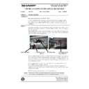
[b] Rush current limit circuit
This circuit limits a rush current which flows into the current regeneration capacitors (C65, C66) which are provided in the document transport motor
(DTM), document reverse motor (DRM), and the document alignment motor (DSM). It is composed of the posistor (PTH1) for limiting the current
and the FET (Q1) fort flowing the current in the normal state.
During the time from when the set switch (SSW) or the cover switch (CSW) is closed to when the ZD3 cathode voltage reaches 12V, the base
current of Q6 is not supplied and it is kept at OFF. Therefore, Q1 is OFF and a current flows through PTH1.
On the other hand, when the ZD3 cathode voltage exceeds 12V, the base current flows through Q6 to turn it on. Therefore Q1 is turned on and the
current flowing through PTH1 flows through Q1, canceling the current limit operation.
R72 and R108 are the discharge resistances for discharging charges accumulated in C65 and C66 when SSW or CSW is opened.
R73 and C58 form the integration circuit which sets the timing of flowing a current through PTH1 when SSW or CSW is closed. D5 is the shot key
diode which discharges the charges of C58. C24 is for absorbing noises. R74 and R80 are the dividing resistors to obtain VGS used to turn on Q1.
[c] Current limit circuit
This circuit is used to limit the starting current of the staple motor at a certain level. It is composed of the resistor for detection of the current value
and the voltage comparator.
The negative voltage side of the motor is connected with the pickup resistance of R99 and R100, and the current flowing through the drive circuit is
converted into a voltage value by this pickup resistor.
The converted voltage value is compared with the reference voltage by the comparator (IC3-1).
The reference voltage is obtained by dividing the zenor voltage generated by R77 and ZD4 with R97 and R98.
When the voltage exceeds this reference level, the output pin 1 of IC3-1 becomes LOW, and the voltage is inputted to the G/A 101 pin to stop
supplying the +24V power to the motor.
Therefore, the current value is not increased further.
When the converted voltage value falls below the reference level, the +24V power is supplied again to start conduction of the motor.
Since the operating current level of this circuit is considerably high, it operates only when the motor starts, and does not operates in the normal
state.
R11 and C30 are for absorbing the noises. R71 is the pull-up resistance.
Rush current limit circuit
+24V
(Power supplied from the main body)
(Power supplied from the main body)
Current limit circuit
11 – 13

