Read Harman Kardon TU 940 Service Manual online
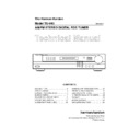
The Harman Kardon
Model TU-940
Manual A
AM/FM STEREO DIGITAL RDS TUNER
CONTENTS
LEAKAGE TEST…………………………...…2
SPECIFICATIONS…………………………....3
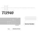
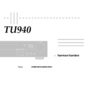
CONTROL AND FUNCTIONS………………4
BLOCK DIAGRAM……………………………7
CONTROL AND FUNCTIONS………………4
BLOCK DIAGRAM……………………………7
DISASSEMBLY PROCEDURES……………8
CIRCUIT DESCRIPTION…………………..13
CIRCUIT DESCRIPTION…………………..13
ALIGNMENT PROCEDURES……………..16
GENERAL UNIT EXPLODED VIEW..…….21
PRINTED CIRCUIT BOARDS…………..…22
ELECTRICAL PARTS LIST……………......24
IC FUNCTIONAL BLOCK DIAGRAM……..32
ELECTRICAL PARTS LIST……………......24
IC FUNCTIONAL BLOCK DIAGRAM……..32
PACKAGE……………………………………33
WIRING DIAGRAM…………………………35
WIRING DIAGRAM…………………………35
SCHEMATIC DIAGRAMS………..………..36
harman/kardon
Parts and Service Office
80 Crossways Park West, Woodbury, N.Y. 11797
Printed in Korea
LOCAL DX
RDS PTY RT CT TA EON TUNED STEREO
MONO TUNING
PRESET
RF LEVEL
STANDBYWIDE
NARROW
CLOCKTIMERON OFF SLEEPAUTOMEMORYSCAN
Power
1
2
3
4
5
6
7
8
9
0
Band
Auto/Man
IF Band
Display
Mode
Memory
TU 940 RDS
Tune/Pst
Pst Scan
Remote sensor
Display
PTY
Direct
Character
Tuning
RF Mode FM Mode
LEAKAGE TEST
Before returning the unit to the user, perform the
following safety checks:
1. Inspect all lead dress to makes certain that leads
following safety checks:
1. Inspect all lead dress to makes certain that leads
are not pinched or that hardware is not lodged
between the chassis and other metallic parts in the
unit.
between the chassis and other metallic parts in the
unit.
2. Be sure that any protective devices such as
nonmetallic control knobs, insulating fishpapers,
cabinet backs, adjustment and compartment covers
or shields, isolation resistor-capacity networks
mechanical insulators, etc. Which were removed for
servicing is properly reinstalled.
cabinet backs, adjustment and compartment covers
or shields, isolation resistor-capacity networks
mechanical insulators, etc. Which were removed for
servicing is properly reinstalled.
3. Be sure that no shock hazard exists; check for
leakage current using Simpson Model 229 Leakage
Tester, standard equipment item no. 21641, RCA
Tester, standard equipment item no. 21641, RCA
model WT 540A or use alternate method as follows:
plug the power cord directly into a 230-volt AC
receptacle ( do not use an isolation transformer for
this test.). Using two clip leads, connects a 1500
ohm, 10-watt resistor paralleled by a 0.15 µF
capacitor, in series with all exposed metal cabinet
parts and a known earth ground such as a water
pipe or conduit. Use a VTVM or VOM with 1000
ohms per volt, or higher sensitivity to measure the
AC voltage drop across the resistor. (This test
should be performed with the power switch in both
the on and off positions.)
A reading of 0.35 volt RMS or more is excessive
and indicates a potential shock hazard which must
be corrected before returning the unit to the owner
2
SPECIFICATION
FM SECTION
Nominal Limit
Test Condition: 40 kHz DEV., 1kHz Frequency.
Tuning Range/Step 87.5 MHz –108 MHz/50 kHz
Usable Sensitivity (-26dB S/N)
Tuning Range/Step 87.5 MHz –108 MHz/50 kHz
Usable Sensitivity (-26dB S/N)
Mono
[
8.15 dBf
[
12.25 dBf
Limiting Sens at –3 dB
[
7.2 dBf
[
9.2 dBf
50dB Quieting Sens
Mono
Mono
[
16.2 dBf
[
19.2 dBf
Stereo
[
39.2 dBf
[
42.8 dBf
Total Harmonic Distortion
Mono
[
0.1%
[
0.25%
Stereo
[
0.15%
[
0.35%
Signal to Noise Ratio (1mV RF INPUT)
Mono
Mono
〈
80 dB
〈
75dB
Stereo
〈
75 dB
〈
70 dB
Stereo Separation at 98 MHz ( NORMAL)
1kHz
〈
50 dB
〈
40 dB
10kHz
〈
40 dB
〈
35 dB
Muting and Automatic Tereshold at 98 MHz
31.2
6
2 dBf 31.2
6
4 dBf
Auto Stop Level 31.2
6
2 dBf 31.2
6
4 dBf
Selectivity NORMAL/NARROW
6
300 kHz
〈
50/70 dB
〈
34/60 dB
Auto Scan Error
6
15 kHz
6
20 kHz
Frequency Response at 30 Hz –15 kHz
6
0.5 dB + 1/
2
2.5 dB
Image Rejection at 106 MHz
〈
80 dB
〈
65dB
AM Suppression
〈
60 dB
〈
50 dB
RDS Sensitivity 31.2
6
2 dBf 31.2
6
4 dBf
Output Voltage
Mono 500
6
100mV 500
6
150mV
DIMENSIOS (W
⋅ H ⋅ D) 442
⋅
92
⋅
350
WEIGHT 3.9 Kg
POWER SUPPLIES AC 230 V, 5-Hz
POWER CONSUMPTION 15W
POWER CONSUMPTION 15W
These specifications are service target specs.
Specifications and components are subject to change without notice.
Overall performance will be maintained or improved.
Specifications and components are subject to change without notice.
Overall performance will be maintained or improved.
AM SECTION
Nominal Limit
Test Condition: 400 Hz, 30% Modulation
Tuning Range/Step
MW 522 kHz – 1611 kHz/9 kHz
Tuning Range/Step
MW 522 kHz – 1611 kHz/9 kHz
Usable Sensitivity (
2
20 dB S/N)
MW: 594 kHz, 1404 kHz
[
500 mV
[
800 mV
Signal to Noise Ratio (0.1 V INPUT)
MW: 999 kHz
MW: 999 kHz
〈
55dB
〈
48 dB
Frequency Response at
2
6 dB
MW 160 Hz ~ 2.5 kHz 150 Hz ~ 2 kHz
Selectivity at
6
9 kHz
MW: 999 kHz
〈
35dB
〈
30 dB
A.G.C. Figure of merit at 999 kHz
〈
50 dB
〈
45 dB
Image Rejection
MW: 1404 kHz
〈
40 dB
〈
35 dB
Total Harmonic Distortion ( 0.1 V INPUT)
MW: 999 kHz
[
0.7%
[
1.2 %
Tuned Level
MW: 999 kHz 800 mV
6
3 dB 800 mV
6
5 dB
Output Voltage ( 5mV INPUT)
165
6
30 mV 165
6
40 mV
3
CONTROL AND FUNCTIONS
1. POWER
Press to turn the unit on. The ring around the button will glow green. Press again to turn the unit
off. The ring will glow red and the word “STANDBY” will appear in the display.
Press to turn the unit on. The ring around the button will glow green. Press again to turn the unit
off. The ring will glow red and the word “STANDBY” will appear in the display.
2. NUMBERIC KEYS
Use to select the preset number of a station that has been entered into the preset memories or
to store a station in the memory in conjunction with MEMORY
Use to select the preset number of a station that has been entered into the preset memories or
to store a station in the memory in conjunction with MEMORY
7
.
To recall a previously programmed station, press the appropriate numeric button(s). For single
digit numbers (1-9), press the number and the station will be tuned at once or in a few seconds.
To recall preset locations 10 though 30, press the desired buttons in order and the station will be
tuned at once.
To use the buttons to enter a station to the preset memory, see page 10.
digit numbers (1-9), press the number and the station will be tuned at once or in a few seconds.
To recall preset locations 10 though 30, press the desired buttons in order and the station will be
tuned at once.
To use the buttons to enter a station to the preset memory, see page 10.
3. FLUORESCENT DISPLAY
The display panel contains a large display for station frequency information and RDS data, as
well as status indicators for various tuner functions and 5-step RF level indicator bars.
The display panel contains a large display for station frequency information and RDS data, as
well as status indicators for various tuner functions and 5-step RF level indicator bars.
4. BAND
Press to change between FM and AM frequency bands..
Press to change between FM and AM frequency bands..
5. IF BAND (FM TUNING ONLY)
Press to change the passband of the intermediate frequency to compensate for interference
form adjacent station.
NARROE: When reception is disturbed by interference from other stations, press until
NARROW is lit. This improves reception.
NORMAL: For normal reception, press until NORMAL is lit.
Press to change the passband of the intermediate frequency to compensate for interference
form adjacent station.
NARROE: When reception is disturbed by interference from other stations, press until
NARROW is lit. This improves reception.
NORMAL: For normal reception, press until NORMAL is lit.
6. DISPLAY MODE
Press to change between bright and dim display lighting or display off.
Press to change between bright and dim display lighting or display off.
LOCAL DX
RDS PTY RT CT TA EON TUNED STEREO
MONO TUNING
PRESET
RF LEVEL
STANDBYWIDE
NARROW
CLOCKTIMERON OFF SLEEPAUTOMEMORYSCAN
Power
1
2
3
4
5
6
7
8
9
0
Band
Auto/Man
IF Band
Display
Mode
Memory
TU 940 RDS
Tune/Pst
Pst Scan
Remote sensor
Display
PTY
Direct
Character
Tuning
RF Mode FM Mode
4 5 6
7
8
9
10
11
12
14
13
15
16
17
3
2
1
4

