Read Sharp AR-FN5 Service Manual online
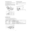
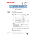
3. Rollers, gates, etc.
No.
Name
Function
1
Paper entry sensor
Detects paper transported from the machine.
2
Transport roller fin
Transports paper in combination with No. 8 roller.
3
Paper entry follower roller (Kick-out
sponge)
sponge)
Transports paper in combination with No. 2 roller.
4
Transport switch gate right
Selects between the escape transport (non-staple mode) and the alignment tray transport (staple
mode).
When selecting the alignment transport (staple mode), this gate drops the rear edge of paper.
mode).
When selecting the alignment transport (staple mode), this gate drops the rear edge of paper.
5
Side guide plate
Aligns paper vertically to the paper transport direction.
6
Upper alignment hold plate
Knocks paper when paper (5th page or later) comes on the alignment tray removing air or adjusting
curls.
curls.
7
Rear edge plate
Aligns paper in the paper transport direction.
8
PS upper roller (Common part)
Transports paper in combination with No. 2, 19, 20 rollers.
9
Paper empty sensor (1A71A)
Detects paper empty on the alignment tray.
10
Shutter
Serves as the paper lead edge reference for alignment of paper, and opens to allow a bundle of
paper to be transported to the paper exit port after stapling.
paper to be transported to the paper exit port after stapling.
11
Transport switch gate left
Selects between the escape tray transport and the offset tray transport.
12
PS upper roller (Common part)
Transports paper in combination with No. 13 roller.
13
Escape transport roller
Transports paper in combination with No. 12 (No. 8) roller.
14
Escape paper exit sensor
Detects paper transport to the escape tray.
15
Transports paper in combination with No. 16 roller.
16
Escape paper exit roller
Transports paper in combination with No. 15 roller.
17
Paper exit roller upper
Transports paper in combination with No. 18 roller. This roller normally follows No. 18 roller. When
discharging a stapled bundle of paper, the electromagnetic clutch turns on to make this roller a drive
roller. The bundle of paper is bent by the difference between this roller speed and the No. 18 roller
speed so that it is not caught by the preceding bundle staple.
discharging a stapled bundle of paper, the electromagnetic clutch turns on to make this roller a drive
roller. The bundle of paper is bent by the difference between this roller speed and the No. 18 roller
speed so that it is not caught by the preceding bundle staple.
18
Paper exit roller lower
Transports (discharges) paper in combination with No. 17 roller.
19
Transport drive roller fin
Transports paper in combination with No. 8 roller.
20
Paper entry roller fin
Transports paper in combination with No. 8 roller.
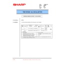
No.
Part name
Code
Function/Operation
Type
22
Transport switch gate solenoid Left
GLSL
Drive to sort paper into the escape paper exit port and the lift-up tray
paper exit port.
paper exit port.
Solenoid
23
Side guide plate alignment motor
SDM
Aligns paper vertically to the paper transport direction.
Pulse motor
24
Reciprocating alignment motor
BKM
Aligns paper in the paper transport direction.
Pulse motor
25
Paper entry sensor
INPD
Detects paper entry in the finisher and detects JAM. Switch trigger of
the transport switch gate right.
the transport switch gate right.
Photo sensor
26
Paper width sensor
WDPD
Make a distinction between A4 and A5R, LT and INVR. If the paper
entry sensor is ON and this sensor is OFF, it is A5R or INVR.
entry sensor is ON and this sensor is OFF, it is A5R or INVR.
Photo sensor
27
Rear edge plate drive solenoid
BKSLD
Drives the rear edge plate.
Solenoid
28
Rear edge plate home position sensor
BKHP
Detects the home position of the rear edge alignment members.
Photo sensor
29
Tray JAM process detection switch
PGSW
Interlocks when the alignment tray is opened downward in a JAM
process.
process.
Micro switch
1
2
3
20
4
5
6
2
19
7
11
9
10
16
15
14
12
13
17
18
8
8
8

