Read Harman Kardon CDR 20 (serv.man17) Technical Bulletin online
harman/kardon, Incorporated
250 Crossways Park Dr. Woodbury, New York 11797
harman/kardon
Service Bulletin
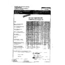
Service bulletin # H/K2001-04 October 2001
Warranty labor rate: MINOR repair
To: All harman/kardon Service Centers
Model: CDR20
Subject: Delay in Reading Blank Disc
In the event you receive a CDR20 CD Player/Recorder with the complaint: “The unit has an excessive
delay (over 45 seconds) when initially reading a blank CDR disc in the Record drawer, after it’s
inserted”, perform the modification below:
Synopsis: Add a 330 pf ceramic capacitor from pin #1 on IC413 Op-amp to Ground.
1) With the unit plugged in, turn it ON. Press the eject button on the Record side to open the drawer.
2) With the drawer fully extended, carefully lift up on the front trim to separate it, and off the main part of the
1) With the unit plugged in, turn it ON. Press the eject button on the Record side to open the drawer.
2) With the drawer fully extended, carefully lift up on the front trim to separate it, and off the main part of the
drawer. Press the eject buton again to close the drawer. Turn the unit OFF and unplug it.
3) Remove the (7) Phillips screws holding the top cover on; remove the top cover.
4) Unplug the three connectors at the rear of the Record PCB.
5) Unscrew the (4) black Phillips screws that are deep in the slotted wells in each corner of the Record
4) Unplug the three connectors at the rear of the Record PCB.
5) Unscrew the (4) black Phillips screws that are deep in the slotted wells in each corner of the Record
mechanism. Lift the entire Record assembly up and out of the unit.
6) Remove the gray metal shield from the assembly. Lay the assembly upside-down on a table, PCB facing
upwards.
7) The PCB can be disengaged from the assembly by depressing the two black plastic tabs on opposite sides of
the PCB and lifting, in sequence.
8) CAREFULLY lift the PCB off the assembly, noting the (4) connectors that are attached to the PCB. Unplug the
three ribbon connectors. (NOTE: the largest female connector on the PCB has a locking collar which must be
lifted to disengage the cable); the mustard-colored molex connector can remain in place, “hinge” the PCB open
enough to lay it flat on the table.
lifted to disengage the cable); the mustard-colored molex connector can remain in place, “hinge” the PCB open
enough to lay it flat on the table.
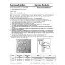
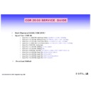
9) Locate the area of concern with the aid of the illustrations. Solder a 330pf ceramic capacitor,
(h/k part# 147-75-331) from electrical equivalent pin #1 on IC431 Op-amp to Ground.
10) Reassemble and replace the record mechanism in reverse order; test the unit by inserting a blank CDR disc in
the Record drawer and note the time delay.
Model
Serial number
120V
Serial number
230V
Status
Action
CDR20
LG0003-01001
to
LG0003-27200
LG0004-01001
to
LG0004-07630
May have long time delay when
reading a blank CDR disc
Add 330 pf capacitor from pin #1
on IC413 Op-amp to Ground
CDR20
LG0003-27201
LG0004-07631
Factory Installed
NONE REQUIRED
Display

