Read Sony DSLR-A700 (serv.man3) Service Manual online
SERVICE MANUAL
LEVEL
2
Ver. 1.2 2008.02
Sony EMCS Co.
9-852-212-81
2008B0500-1
© 2008.2
Published by Kohda TEC
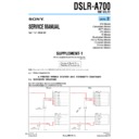
SUPPLEMENT-1
File this supplement with the service manual.
(DI07-267)
• Change of Repair Parts
• Revision of Accessories
• Revision of Accessories
US Model
Canadian Model
AEP Model
UK Model
E Model
Australian Model
Hong Kong Model
Chinese Model
Korea Model
Japanese Model
DSLR-A700
RMT-DSLR1
DSLR-A700_L2
Note:
Please refer to Ver. 1.2 of SERVICE MANUAL (9-852-212-32) for the revision of accessories.
: Points changed portion.
4. PRINTED WIRING BOARDS AND SCHEMATIC DIAGRAMS
4-2. SCHEMATIC DIAGRAMS
MA-448 FLEXIBLE BOARD (2/2) (CONNECTOR)
(Service manual page 4-38, Location B-4 to D-6)
Former
New
CN5910
8P
1
PGND
2
PGND
3
PGND
4
PGND
5
LVDD0
6
LVDD0
7
LVDD0
8
LVDD0
CN5903
6P
1
LSOUT
2
REG_GND
3
CSLNS
4
LSCK
5
LVDD1
6
LSIN
D5906
1
2
3
D5908
DF3A6.8FE(TPL3)
1
2
3
XX
CN5910
8P
1
PGND
2
PGND
3
PGND
4
PGND
5
LVDD0
6
LVDD0
7
LVDD0
8
LVDD0
CN5903
6P
1
LSOUT
2
REG_GND
3
CSLNS
4
LSCK
5
LVDD1
6
LSIN
D5906
DF3A6.8FE(TPL3)
1
2
3
D5908
DF3A6.8FE(TPL3)
1
2
3
— 2 —
DSLR-A700_L2
Page
Former
New
Ref. No.
Part No.
Description
Ref. No.
Part No.
Description
5-5
2
2-688-728-01 CAP, BODY
157
3-274-514-01 CUSHION, STOP
#94
2-515-483-31 SCREW (M1.7), LOCK ACE, P2 (Black)
2
2-688-728-02 CAP, BODY
157
3-274-514-03 CUSHION, STOP
#10
2-599-475-31 SCREW(M1.7) (Silver)
306
3-290-178-01 GUARD SHEET, TP FLEX
5-2
&
: Points added portion.
: Points changed portion.
: Points changed portion.
5. REPAIR PARTS LIST
5-1. EXPLODED VIEWS
#5
#10
#10
159
160
160
#5
#94
#94
159
160
160
#12
#12
#94
#84
#84
304
303
#12
#12
#94
#84
#84
304
306
303
)
5-8
— 3 —
DSLR-A700_L2
Page
Former
New
Ref. No.
Part No.
Description
Ref. No.
Part No.
Description
555
2-695-354-01 WASHER (Note 3)
#76
2-666-551-11 SCREW,TAPPING,P2 (Silver)
555
3-292-847-01 WASHER (Note 3)
5-12
: Points changed portion.
#85
ns
ns
#5
#5
Tebure Unit Section
(See page 5-13)
(See page 5-13)
#85
ns
ns
#76
#76
Tebure Unit Section
(See page 5-13)
(See page 5-13)
5-13
#87
#87
#87
555
555
555
Slider Unit
Washer
Note 3: Note the direction when you install washers.
(It corresponds to both of old and new parts)
Setting washers like that round
chamfering is rear side.
chamfering is rear side.
— 4 —
DSLR-A700_L2
5-2. ELECTRICAL PARTS LIST
Page
Former
New
Ref. No.
Part No.
Description
Ref. No.
Part No.
Description
5-28
A-1317-981-A GY-003 FLEXIBLE BOARD, COMPLETE
*******************************
< SENSOR >
SE6201 1-480-049-11 SENSOR, ANGULAR VELOCITY (PITCH)
SE6202 1-480-049-11 SENSOR, ANGULAR VELOCITY (YAW)
SE6202 1-480-049-11 SENSOR, ANGULAR VELOCITY (YAW)
A-1317-979-A MA-448 FLEXIBLE BOARD, COMPLETE
*******************************
< DIODE >
D5906
8-719-081-73 DIODE DF3A6.8FE (TPL3)
< FUSE >
0 F5901
1-576-407-21 FUSE (1.4A/36V)
A-1317-981-A GY-003 FLEXIBLE BOARD, COMPLETE
*******************************
< SENSOR >
SE6201 1-480-049-31 SENSOR, ANGULAR VELOCITY (PITCH)
SE6202 1-480-049-31 SENSOR, ANGULAR VELOCITY (YAW)
SE6202 1-480-049-31 SENSOR, ANGULAR VELOCITY (YAW)
A-1317-979-A MA-448 FLEXIBLE BOARD, COMPLETE
*******************************
< DIODE >
< FUSE >
0 F5901
1-576-406-11 FUSE (1.4A/32V)
5-28
The components identified by
mark 0 or dotted line with
mark 0 are critical for safety.
Replace only with part number
specified.
mark 0 or dotted line with
mark 0 are critical for safety.
Replace only with part number
specified.
Les composants identifiés par une
marque 0 sont critiques pour la
sécurité.
Ne les remplacer que par une pièce
portant le numéro spécifié.
marque 0 sont critiques pour la
sécurité.
Ne les remplacer que par une pièce
portant le numéro spécifié.
0印の部品,または0印付きの点線で囲まれた部品は,
安全性を維持するために重要な部品です。
従って交換時は,必ず指定の部品を使用して下さい。
安全性を維持するために重要な部品です。
従って交換時は,必ず指定の部品を使用して下さい。
&
: Points added portion.
: Points changed portion.
: Points changed portion.
Page
Former
New
Ref. No.
Part No.
Description
Ref. No.
Part No.
Description
5-14
#5
3-080-204-01 SCREW, TAPPING, P2 (Black)
653
3-099-776-01 SCREEN, SI (Note 1)
658
3-209-524-01 FOCUSING SCREEN (Note 1)
661
3-278-777-01 SI SCREEN (TYPE L) (Note 1)
662
3-278-776-01 FOCUSING SCREEN (TYPE M) (Note 1)
612
3-870-313-01 SHEET, AFM FLEXIBLE GUARD
#76
2-666-551-11 SCREW,TAPPING,P2 (Silver)
653
A-1497-518-A SI SCREEN (SERVICE) (Note 1)
658
A-1497-520-A FOCUSING SCREEN (SERVICE) (Note 1)
661
A-1497-519-A SI SCREEN (L) (SERVICE) (Note 1)
662
A-1497-521-A FOCUSING SCREEN (M) (SERVICE)
(Note 1)
5-15
#5
605
#88
601
603
603
603
602
(including AF-110 flexible board)
605
#88
601
603
603
612
603
602
(including AF-110 flexible board)
#76
)

