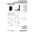
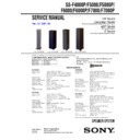
Read Sony DAV-F200 / DAV-F500 / SA-WSF200 / SA-WSF500 / SS-CTF500 / SS-F500 / SS-TSF200 / SS-TSF500 Service Manual online
SERVICE MANUAL
Sony Corporation
Audio&Video Business Group
Published by Sony Techno Create Corporation
SA-WSF200/WSF500/
SS-CTF500/F500/TSF200/TSF500
SPECIFICATIONS
SA-WSF200/WSF500
ACTIVE SUBWOOFER
SS-CTF500/TSF200/TSF500
SPEAKER SYSTEM
9-889-149-02
2008H05-1
©
2008.08
Canadian Model
E Model
Australian Model
Russian Model
SA-WSF500/SS-CTF500/F500/TSF500
AEP Model
UK Model
SA-WSF200/SS-TSF200
Singapore Model
Thai Model
SA-WSF200/WSF500/
SS-CTF500/F500/TSF200/TSF500
Ver. 1.1 2008.08
Photo: SA-WSF500
Photo: SS-CTF500
Photo: SS-TSF200
Photo: SS-TSF500
• SA-WFS200 is the active subwoofer in DAV-F200.
• SA-WFS500 is the active subwoofer in DAV-F500.
• SS-CTF500 is the center speaker in DAV-F500.
• SS-TSF200 is the front speaker in DAV-F200.
• SS-TSF500 is the front and Surround speaker in DAV-F500.
• SS-F500 is composed of four SS-TSF500, one SS-CTF500, four Speaker stands and Wall mounting brackets. (for DAV-F500)
Note:
• When SA-WSF200 is checked, it is necessary to connect it with HCD-F200.
• When SA-WSF500 is checked, it is necessary to connect it with HCD-F500.
Speakers
Front speaker (SS-TSF200)
Front speaker (SS-TSF200)
Speaker system
2-Way 2-Driver speaker
system Bass reflex,
Magnetically Shielded
system Bass reflex,
Magnetically Shielded
Speaker unit
Woofer: 65 mm cone type
Tweeter: 40 mm cone type
Tweeter: 40 mm cone type
Rated impedance
3 ohms
Dimensions (approx.)
95 mm × 185 mm × 80 mm
(w/h/d)
95 mm × 215 mm × 105
mm (w/h/d) with stand
(w/h/d)
95 mm × 215 mm × 105
mm (w/h/d) with stand
Mass (approx.)
0.85 kg
0.9 kg with stand
0.9 kg with stand
Subwoofer (SA-WSF200)
Power requirements:
Power consumption
On: 105 W
Standby: 0.3 W (at the
Power Saving mode)
Standby: 0.3 W (at the
Power Saving mode)
Speaker system
Subwoofer Bass reflex
Speaker unit
160 mm cone type
Rated impedance
3 ohms
Dimensions (approx.)
205 mm × 460 mm × 475
mm (w/h/d)
mm (w/h/d)
Mass (approx.)
13 kg
Speakers
Front and Surround speaker (SS-TSF500)
Front and Surround speaker (SS-TSF500)
Speaker system
2-Way 3-Driver speaker
system Bass reflex,
Magnetically Shielded
system Bass reflex,
Magnetically Shielded
Speaker unit
Woofer: 65 mm cone type
× 2
Tweeter: 50 mm cone type
× 2
Tweeter: 50 mm cone type
Rated impedance
3 ohms
Dimensions (approx.)
95 mm × 635 mm × 80 mm
(w/h/d)
305 mm × 1,205 mm × 305
mm (w/h/d) with stand
(w/h/d)
305 mm × 1,205 mm × 305
mm (w/h/d) with stand
Mass (approx.)
1.8 kg
5.3 kg with stand
5.3 kg with stand
Center speaker (SS-CTF500)
Speaker system
Full range, Magnetically
Shielded
Shielded
Speaker unit
30 mm × 50 mm cone type
Rated impedance
3 ohms
Dimensions (approx.)
381 mm × 48 mm × 62 mm
(w/h/d)
(w/h/d)
Mass (approx.)
0.5 kg
Amplifier Section
Power output (rated)
RMS output power (reference)
108 W + 108 W (at 3 ohms,
1 kHz, 1% THD)
1 kHz, 1% THD)
FL/FR/C*: 141 W
(per channel at 3 ohms,
1 kHz, 10% THD)
Subwoofer*: 141 W (at 3
ohms, 80 Hz, 10% THD)
(per channel at 3 ohms,
1 kHz, 10% THD)
Subwoofer*: 141 W (at 3
ohms, 80 Hz, 10% THD)
* Depending on the decoding mode settings and the
source, there may be no sound output.
source, there may be no sound output.
Thai model:
220 V AC, 50/60 Hz
Other models:
220 V – 240 V AC, 50/60 Hz
– Continued on next page –
SA-WSF200/WSF500/SS-CTF500/F500/TSF200/TSF500
2
1.
SERVICING NOTES
............................................. 3
2. GENERAL
.................................................................. 7
3. DISASSEMBLY
3-1. Disassembly Flow (SA-WSF200/WSF500) ................... 8
3-2. Amp Complete Assy (SA-WSF200/WSF500) ............... 9
3-3. Loudspeaker (16 cm) (SP001)
(SA-WSF200/WSF500)
3-2. Amp Complete Assy (SA-WSF200/WSF500) ............... 9
3-3. Loudspeaker (16 cm) (SP001)
(SA-WSF200/WSF500)
..................................................
9
3-4. Back Panel (WS) (SA-WSF200/WSF500) ..................... 10
3-5. Speaker Board, Terminal Board (WS)
(SA-WSF200/WSF500)
3-5. Speaker Board, Terminal Board (WS)
(SA-WSF200/WSF500)
..................................................
10
3-6. AMP-DSP Board (SA-WSF200/WSF500) ..................... 11
3-7. POWER Board (SA-WSF200/WSF500) ........................ 11
3-7. POWER Board (SA-WSF200/WSF500) ........................ 11
4. DIAGRAMS
4-1. Block
Diagram
- DSP Section (SA-WSF200/WSF500) - ........................ 12
4-2. Block
Diagram
- AMP Section (SA-WSF200/WSF500) - ....................... 13
4-3. Block Diagram - POWER SUPPLY Section
(SA-WSF200/WSF500)
(SA-WSF200/WSF500)
-
...............................................
14
4-4. Printed Wiring Board - AMP-DSP Board
(Component Side) (SA-WSF200/WSF500) - ................. 16
4-5. Printed Wiring Board - AMP-DSP Board
(Conductor Side) (SA-WSF200/WSF500) - ................... 17
4-6. Schematic
Diagram
- AMP-DSP Board (1/3) (SA-WSF200/WSF500) - ........ 18
4-7. Schematic
Diagram
- AMP-DSP Board (2/3) (SA-WSF200/WSF500) - ........ 19
4-8. Schematic
Diagram
- AMP-DSP Board (3/3) (SA-WSF200/WSF500) - ........ 20
4-9. Printed
Wiring
Boards
- SPEAKER Section (SA-WSF200/WSF500) - ............. 21
4-10. Schematic Diagram
- SPEAKER Section (SA-WSF200/WSF500) - ............. 21
4-11. Printed Wiring Board
- POWER Board (SA-WSF200/WSF500) - ................... 22
4-12. Schematic Diagram
- POWER Board (SA-WSF200/WSF500) - ................... 23
4-13. Printed Wiring Board
- REG Board (SA-WSF200/WSF500) - ......................... 24
4-14. Schematic Diagram
- REG Boards (SA-WSF200/WSF500) - ........................ 24
5.
EXPLODED VIEWS
5-1. Cabinet Section (SA-WSF200/WSF500) ....................... 36
5-2. AMP Complete Assy (SA-WSF200/WSF500) ............... 37
5-3. AMP Board Section (SA-WSF200/WSF500)................. 38
5-4. POWER board Section (SA-WSF200/WSF500) ............ 39
5-5. SS-CTF500/TSF200/TSF500
5-2. AMP Complete Assy (SA-WSF200/WSF500) ............... 37
5-3. AMP Board Section (SA-WSF200/WSF500)................. 38
5-4. POWER board Section (SA-WSF200/WSF500) ............ 39
5-5. SS-CTF500/TSF200/TSF500
......................................... 40
8-6. Speaker Stand (for SS-TSF500) ..................................... 41
6.
ELECTRICAL PARTS LIST
.............................. 42
TABLE OF CONTENTS
NOTES ON CHIP COMPONENT REPLACEMENT
•
•
Never reuse a disconnected chip component.
•
Notice that the minus side of a tantalum capacitor may be dam-
aged by heat.
aged by heat.
SAFETY-RELATED COMPONET WARNING!
COMPONENTS IDENTIFIED BY MARK 0 OR DOTTED LINE
WITH MARK 0 ON THE SCHEMATIC DIAGRAMS AND IN
THE PARTS LIST ARE CRITICAL TO SAFE OPERATION.
REPLACE THESE COMPONENTS WITH SONY PARTS
WITH MARK 0 ON THE SCHEMATIC DIAGRAMS AND IN
THE PARTS LIST ARE CRITICAL TO SAFE OPERATION.
REPLACE THESE COMPONENTS WITH SONY PARTS
WHOSE PART NUMBERS APPEAR AS SHOWN IN THIS
MANUAL OR IN SUPPLEMENTS PUBLISHED BY SONY.
MANUAL OR IN SUPPLEMENTS PUBLISHED BY SONY.
ATTENTION AU COMPOSANT AYANT RAPPORT
À LA SÉCURITÉ!
LES COMPOSANTS IDENTIFIÉS PAR UNE MARQUE 0 SUR
LES DIAGRAMMES SCHÉMATIQUES ET LA LISTE DES
PIÈCES SONT CRITIQUES POUR LA SÉCURITÉ DE FONC-
TIONNEMENT. NE REMPLACER CES COMPOSANTS QUE
PAR DES PIÈCES SONY DONT LES NUMÉROS SONT DON-
NÉS DANS CE MANUEL OU DANS LES SUPPLÉMENTS
PUBLIÉS PAR SONY.
LES DIAGRAMMES SCHÉMATIQUES ET LA LISTE DES
PIÈCES SONT CRITIQUES POUR LA SÉCURITÉ DE FONC-
TIONNEMENT. NE REMPLACER CES COMPOSANTS QUE
PAR DES PIÈCES SONY DONT LES NUMÉROS SONT DON-
NÉS DANS CE MANUEL OU DANS LES SUPPLÉMENTS
PUBLIÉS PAR SONY.
Accessories are given in the last of the electrical parts list.
Subwoofer (SA-WSF500)
Power requirements:
Canadian and Mexican models:
Canadian and Mexican models:
120 V AC, 60 Hz
Taiwan model:
120 V AC, 50/60 Hz
Latin American model:
110 V – 240 V AC, 50/60 Hz
Korean model:
220 V AC, 60 Hz
Thai model:
220 V, 50/60 Hz
Other models:
220 V – 240 V AC, 50/60 Hz
Power consumption
On: 135 W
Standby: 0.3 W (at the
Power Saving mode)
Standby: 0.3 W (at the
Power Saving mode)
Speaker system
Subwoofer Bass reflex
Speaker unit
160 mm cone type
Rated impedance
3 ohms
Dimensions (approx.)
205 mm × 460 mm × 475
mm (w/h/d)
mm (w/h/d)
Mass (approx.)
13 kg
Design and specifications are subject to change
without notice.
without notice.
Amplifier Section
Power output (rated)
RMS output power (reference)
108 W + 108 W (at 3 ohms,
1 kHz, 1% THD)
1 kHz, 1% THD)
FL/FR/C*: 141 W
(per channel at 3 ohms,
1 kHz, 10% THD)
Subwoofer*: 141 W (at 3
ohms, 80 Hz, 10% THD)
(per channel at 3 ohms,
1 kHz, 10% THD)
Subwoofer*: 141 W (at 3
ohms, 80 Hz, 10% THD)
* Depending on the decoding mode settings and the
source, there may be no sound output.
Ver. 1.1
SA-WSF200/WSF500/SS-CTF500/F500/TSF200/TSF500
3
UNLEADED SOLDER
Boards requiring use of unleaded solder are printed with the lead-
free mark (LF) indicating the solder contains no lead.
(Caution: Some printed circuit boards may not come printed with
Boards requiring use of unleaded solder are printed with the lead-
free mark (LF) indicating the solder contains no lead.
(Caution: Some printed circuit boards may not come printed with
the lead free mark due to their particular size)
: LEAD FREE MARK
Unleaded solder has the following characteristics.
• Unleaded solder melts at a temperature about 40 °C higher
• Unleaded solder melts at a temperature about 40 °C higher
than ordinary solder.
Ordinary soldering irons can be used but the iron tip has to be
applied to the solder joint for a slightly longer time.
applied to the solder joint for a slightly longer time.
Soldering irons using a temperature regulator should be set to
about 350 °C.
Caution: The printed pattern (copper foil) may peel away if
about 350 °C.
Caution: The printed pattern (copper foil) may peel away if
the heated tip is applied for too long, so be careful!
• Strong
viscosity
Unleaded solder is more viscous (sticky, less prone to fl ow)
than ordinary solder so use caution not to let solder bridges
occur such as on IC pins, etc.
than ordinary solder so use caution not to let solder bridges
occur such as on IC pins, etc.
•
Usable with ordinary solder
It is best to use only unleaded solder but unleaded solder may
also be added to ordinary solder.
also be added to ordinary solder.
SECTION 1
SERVICING NOTES
BEGIN IT BEFORE THE REPAIR (SA-WSF200)
When the SA-WSF200 is checked, connect to HCD-F200 (for
DVD receiver of DAV-F200). Be sure in advance the HCD-F200
is prepared.
When the SA-WSF200 is checked, connect to HCD-F200 (for
DVD receiver of DAV-F200). Be sure in advance the HCD-F200
is prepared.
BEGIN IT BEFORE THE REPAIR (SA-WSF500)
When the SA-WSF500 is checked, connect to HCD-F500 (for
DVD receiver of DAV-F500). Be sure in advance the HCD-F500
is prepared.
When the SA-WSF500 is checked, connect to HCD-F500 (for
DVD receiver of DAV-F500). Be sure in advance the HCD-F500
is prepared.
MODEL IDENTIFICATION (SA-WSF200/WSF500)
Model
Part No.
SA-WSF200: AEP and UK models
3-294-285-0[]
SA-WSF200: Singapore model
3-294-286-0[]
SA-WSF500: Canadian model
3-294-289-0[]
SA-WSF500: Russian model
3-294-291-0[]
SA-WSF500: Singapore model
3-294-292-0[]
SA-WSF500: 240V AC area in E
and Iranian models
and Iranian models
3-294-293-0[]
SA-WSF500: Thai model
3-294-295-0[]
SA-WSF500: Australian model
3-294-297-0[]
SA-WSF500: Korean model
3-294-298-0[]
SA-WSF500: Latin American model
(110 – 240V AC area)
3-294-299-0[]
SA-WSF500: Mexican model
3-294-300-0[]
SA-WSF500: Taiwan model
3-294-301-0[]
SA-WSF200: Thai model
3-452-614-0[]
SA-WSF500: Saudi Arabia model
4-114-165-0[]
Part No.
– Rear View –
Ver. 1.1
SA-WSF200/WSF500/SS-CTF500/F500/TSF200/TSF500
4
BOND FIXATION OF ELECTRIC PARTS (SA-WSF200/WSF500)
When AMP-DSP, POWER and SPEAKER boards are exchanged or the following object parts are exchanged, it is necessary to fi x parts to
the substrate by using a specifi ed bond without fail.
When AMP-DSP, POWER and SPEAKER boards are exchanged or the following object parts are exchanged, it is necessary to fi x parts to
the substrate by using a specifi ed bond without fail.
• Object boards
Board name
Part No.
AMP-DSP
A-1508-649-A (SA-WSF200: AEP and UK models)
A-1508-673-A (SA-WSF200: Singapore and Thai models)
A-1508-692-A (SA-WSF500: Russian model)
A-1508-695-A (SA-WSF500: Canadian model)
A-1508-698-A (SA-WSF500: Singapore , Taiwan and Thai models)
A-1508-713-A (SA-WSF500: Korean model)
A-1508-716-A (SA-WSF500: 240V AC area in E, Iranian and Saudi Arabia models)
A-1508-719-A (SA-WSF500: Australian)
A-1508-722-A (SA-WSF500: Latin American model (110 – 240V AC area))
A-1508-738-A (SA-WSF500: Mexican model)
POWER
A-1508-660-A (SA-WSF200: AEP and UK models/SA-WSF500: Russian model)
A-1508-670-A (SA-WSF500: Canadian model)
A-1508-676-A (SA-WSF200: Singapore model/
SA-WSF500: 240V AC area in E, Iranian, Singapore and Australian models)
SPEAKER
A-1508-652-A (SA-WSF200)
A-1508-687-A (SA-WSF500)
• Object parts
Board name
Part No.
AMP-DSP
C307, C309, C317, C327, C329, C337, C407, C409, C417, L323, L403, L553 (SA-WSF200/WSF500)
C387, C389, C397, L383 (SA-WSF500)
C387, C389, C397, L383 (SA-WSF500)
POWER
C902, C905, C908, C910, C913, C927, C928, C929, C932, C933, C940, C963, C964, D901, LF901, LF902, TH901,
VDR901
VDR901
SPEAKER
L101, L102, L103, L104
• Use bond
7-432-912-52 BOND, SONY (SC-608LV)
7-432-912-52 BOND, SONY (SC-608LV)
• Parts position
Note: Picture used is SA-WSF500.
C317
C407 C409 C387 C389 C327 C329 C307 C309
L553
L323
L383
L403
C337
C397
C417
– AMP-DSP Board (Component Side) –
bond
bond
bond
bond
bond
bond
bond
bond
Ver. 1.1


