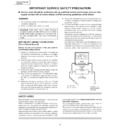
Read Sharp PZ-50HV2E (serv.man4) Service Manual online
7
PZ-50HV2, PZ-50HV2E
PZ-50HV2U
PZ-50HV2U
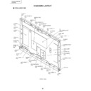
CHARGED SECTION AND HIGH VOLTAGE GENERATING POINT
Ë
Charged Section
1. AC Power Cord
2. AC Inlet with Filter
3. Power Switch (S1)
4. Fuse (In the SW POWER SUPPLY Module)
5. STB Transformer and Converter Transformer
(In the SW POWER SUPPLY Module)
6. Other primary side of the SW POWER SUPPLY Module
2. AC Inlet with Filter
3. Power Switch (S1)
4. Fuse (In the SW POWER SUPPLY Module)
5. STB Transformer and Converter Transformer
(In the SW POWER SUPPLY Module)
6. Other primary side of the SW POWER SUPPLY Module
Ë
High Voltage Generating Point
The places where voltage is 100V or more except for the
charged places described above. If the places are touched,
there is a risk of electric shock.
charged places described above. If the places are touched,
there is a risk of electric shock.
1. SW POWER SUPPLY Module .............................. (225V)
2. X DRIVE Assy ....................................... (–300V to 225V)
3. Y DRIVE Assy ....................................................... (355V)
4. SCAN (A) Assy ...................................................... (355V)
5. SCAN (B) Assy ...................................................... (355V)
6. X CONNECTOR (A) Assy ..................... (–300V to 225V)
7. X CONNECTOR (B) Assy ..................... (–300V to 225V)
AC Inlet with Filter
Power Cord
Power Switch
(S1)
(S1)
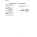
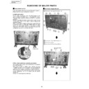
Fig.1 Charged Section and High Voltage Generating Point (Rear View)
: Part is the High Voltage Generating Points
other than the Charged Section.
other than the Charged Section.
: Part is Charged Section.
X DRIVE
Assy
Assy
X CONNECTOR (B)
Assy
Assy
Y DRIVE
Assy
Assy
SCAN (A)
Assy
Assy
SCAN (B)
Assy
Assy
∗
Remove the IF Earth Metal beforehand when inclines
the power supply unit as the right figure.
the power supply unit as the right figure.
X CONNECTOR (A)
Assy
Assy
SW POWER SUPPLY
Module
Module
Top
Front

