Read Sharp PZ-50HV2E (serv.man9) Service Manual online
35
PZ-50HV2, PZ-50HV2E
PZ-50HV2U
PZ-50HV2U
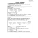
TROUBLE DIAGNOSIS
• Operations : When a microcomputer detected abnormality, turn the power supply to OFF.
• LED display : Green blinks
• LED display : Green blinks
How to release the shut down state
When turn the power supply ON by remote control units, release from the
shut down state, and turn the power supply ON.
(It is not necessary to turn the AC power OFF.)
shut down state, and turn the power supply ON.
(It is not necessary to turn the AC power OFF.)
How to release the power down state
AC power OFF
↓
Wait for PD LED in the power supply module disappearing
(for around 30 seconds).
(for around 30 seconds).
↓
Afterwards, wait moreover for five seconds.
↓
Return by AC power ON.
* After power down release, this unit rises up in the standby state.
* After power down release, this unit rises up in the standby state.
Examples: LED blinks in the DIGITAL-IIC communication NG
• Operations : When this unit becomes the dangerous state, turn the power supply OFF with the protection circuit.
• LED display : Red blinks
* When protection circuit more than two places almost worked simultaneously, display LED in order to 1st - 2nd.
• LED display : Red blinks
* When protection circuit more than two places almost worked simultaneously, display LED in order to 1st - 2nd.
Examples: LED blinks in the 1st power down = Y-DC/DC CONVERTER, 2nd power down = Y-DRIVE
Number of
blinks
Name
1
Panel Microcomputer NG
2
DIGITAL-IIC communication NG
3
Dewdrop abnormality
4
Temperature abnormality
Number of
blinks
Name
1
Y-DRIVE
2
Y-DC/DC CONVERTER
3
X-DC/DC CONVERTER
4
X-DRIVE
5
Power supply
6
Address junction
7
Address resonance
8
DIGITAL-DC/DC CONVERTER
SHUT DOWN/POWER DOWN DIAGNOSIS BY LED DISPLAY
Shut Down
Power Down
Green LED lights
for 200 msec.
Lights out
for 3 sec
Green LED lights
for 200 msec.
Lights out
for 100 msec
When internal circuit abnormality and other operation abnormality occurred from this unit, self-diagnose display function by
STANDBY/ON (LED) indicator is loaded.
Each NG point by LED blinking and a PD (power down) point are as follows.
STANDBY/ON (LED) indicator is loaded.
Each NG point by LED blinking and a PD (power down) point are as follows.
1st power-down information
2nd power-down
information
Red LED lights
for 200 msec.
Lights out
for 3 sec
Lights out
for 1 sec
Red LED lights
for 200 msec.
Lights out
for 100 msec
Red LED lights
for 200 msec.
36
PZ-50HV2, PZ-50HV2E
PZ-50HV2U
PZ-50HV2U
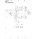
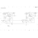
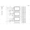
Block Diagram of Shut Down Signal System
Note:
1
-
4
show LED flashing number of times when shut down occurred in this route.
RXD
BUSY
REQ_PU
TXD
CLK
*PU_CE
DEW_DET
CN2002
TEMP1
DIGITAL VIDEO ASSY
THERMAL SENSOR
ASSY
ASSY
Y DRIVE ASSY
SW POWER SUPPLY
MODULE
MODULE
MR INTERFACE ASSY
AUDIO ASSY
AVC SYSTEM
IC1191
Panel UCOM
external Flash ROM
IC1204
EEPROM
IC1101
Panel UCOM
IC1207
Module UCOM
IC4204
SiI861
IC5202
CXA2021S
IC4005
Expander
IC4011
Expander
Expander
SCL
SDA
A_SCL
A_SDA
A_SDA
DDC_SCL
DDC_SDA
DDC_SDA
D1
D3
P2
R3
D18
TE1
D6
Y2
1
4
3
2
2
2
IC8351
Thermal
Sensor 1
Moisture
Sensor
37
PZ-50HV2, PZ-50HV2E
PZ-50HV2U
PZ-50HV2U
When a module microcomputer failed in communication with a panel
microcomputer, this NG occurs.
Shut down after OSD display for 30 seconds from the NG detection.
microcomputer, this NG occurs.
Shut down after OSD display for 30 seconds from the NG detection.
Abnormality to expect
Open / Short of communication line in the Assy
Open / Short of communication line in the Assy
1
Panel microcomputer NG
When a module microcomputer failed in communication with outside
EEPROM or EXPANDER, this NG occurs.
Shut down after OSD display for 30 seconds from the NG detection.
* However, this communication NG may occur in the standby state.
EEPROM or EXPANDER, this NG occurs.
Shut down after OSD display for 30 seconds from the NG detection.
* However, this communication NG may occur in the standby state.
Abnormality to expect
• Open / Short of communication line in the DIGITAL VIDEO, MR INTERFACE
• Open / Short of communication line in the DIGITAL VIDEO, MR INTERFACE
and AUDIO Assys
• Breaking of wire of the following points is thought about.
DIGITAL VIDEO Assy (D1)
↔
SW POWER SUPPLY Module (P2)
DIGITAL VIDEO Assy (D3)
↔
MR INTERFACE Assy (R3)
MR INTERFACE Assy (R23)
↔
AUDIO Assy (A24)
System Cable
2
DIGITAL-IIC communication NG
When it becomes the dew drop state in this unit, this NG occurs.
After the dew drop detection, shut down immediately.
After the dew drop detection, shut down immediately.
Abnormality to expect for dew drop
Disconnect a connector CN2002 between Dew drop sensor and Y DRIVE Assy.
Disconnect a connector CN2002 between Dew drop sensor and Y DRIVE Assy.
3
Dew drop detection
When temperature of this unit became abnormally high, this NG occurs.
Shut down after OSD display from the NG detection for 30 seconds.
Note: When temperature fell down during indication, return to the normal operation.
Shut down after OSD display from the NG detection for 30 seconds.
Note: When temperature fell down during indication, return to the normal operation.
Abnormality to expect when it occurs in the environment that is not
high-temperature
• Disconnect a connector between DIGITAL VIDEO Assy (D18) and
high-temperature
• Disconnect a connector between DIGITAL VIDEO Assy (D18) and
temperature sensor 1 (TE1).
Shut down temperature of each temperature sensor
Sensor Temp 78
Sensor Temp 78
4
Temperature abnormality
Reference
Shut down diagnosis
1
2
3
4
5
6
7
8
9
2
3
4
5
6
7
8
9
10
11
12
13
14
15
16
17
18
11
12
13
14
15
16
17
18
CENTE
1 / 1 3
R Ve r s
OSD Ve r s i o n
CV I C Ve r s i o n
CV I C Ve r s i o n
TTXP Ve r s i o n
i on
MON I TOR Ve r s i on
Mod e l S l e
e
c t
i n
Ma
Mod e l S l e
e
c t AV
Mod e l S l e
e
c t
Ce n t e r
c u
A
t i me
MON I TOR
RESET
RESET
OFF
RESET
OFF
OFF
+
0
0
4
4
2 8
F 6 9 1 1 0
TTX
R
P G
W2 0 0 /
1 0 9
0
0 0
9 :
1 2
/
X2 0 0 /
1 0 9
0
0 7
9 :
1 2
/
V2 0
0 6 1
0 /
1 0 9
0
1 0
9 :
1 2
/
MR O D
S
2
0
1 0
9
A
/
/
0 1
0
MR M I
A N
0 0
2
1
E
- 0 5
- 0 0
PANEL Ve r s i on
FLASH Ve r s i on
FLASH Ve r s i on
MON I TOR Mo de l
Mon i t o r Ac u t i me
4 7
H
4 2 M
H
4 1 M
1 6
0 1
Pu l s e Ac u t i me
1 6 4
Se n s o r e Temp
0
2 5 H
9 /
/
NP
I
U
S
1
G
I
No
T
E06
E06
E04
38
PZ-50HV2, PZ-50HV2E
PZ-50HV2U
PZ-50HV2U
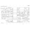
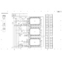
Block Diagram of Power Down Signal System
Address PD
Mute
DIGITAL
DC-DC
X Drive
X DC-DC
OR
OR
PD Circuit
Y Drive
Y DC-DC
OR
Relay
Circuit
AND
OR
OR
OR
D8
D11
8
6
7
4
5
1
2
3
ADR CONNECT
ASSY
(Upper)
DIGITAL VIDEO ASSY
SW POWER
SUPPLY
MODULE
X DRIVE ASSY
Y DRIVE ASSY
ADR CONNECT
ASSY
(Lower)
RESONANCE
ASSY
(Upper)
RESONANCE
ASSY
(Lower)
-
D12
D16
D1
X1
P4
P2
P3
Y1
D17
D15
-
IC1201-pin 8
IC1201-pin 6
D1202 Cathode
DIG_ADR.PD
PD_TRIGGER
Note:
1
-
8
show LED flashing number of times when power down occurred in this route.

