Read Sharp LC-37D44EBK (serv.man4) Service Manual online
LC-37D44E/S/RU-BK/GY
2 – 1
LC37D44E-BK
Service Manual
CHAPTER 2.
REMOVING OF MAJOR PARTS
[1] REMOVING OF MAJOR PARTS
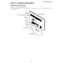
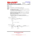
1. Remove the 4 lock screws
and detach the Stand
.
2. Remove the PC Card Cover
, 1 lock screw
, 2 lock screws
, 6 lock screws
,4 lock screws
, 2 VESA Caps
and 2 lock screws
and detach the Rear Cabinet.
1
2
3
4
5
6
7
8
9
1
8
2
5
9
4
6
3
7
Stand
Front Cabinet
Rear Cabinet
PC Card Cover
LC-37D44E/S/RU-BK/GY
2 – 2
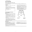
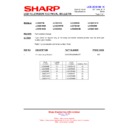
3. Disconnect the KM, LB, PD, SP, RA connectors and FFCs.
4. Remove the Speaker (L)
, Speaker (R)
.
5. Remove the LED PWB Unit
.
6. Remove the Control Button
.
7. Remove the KEY PWB Unit
from Control Button.
8. Remove the 8 lock screws
and detach the LCD PANEL from the Front Cabinet.
10
11
12
13
14
15
LED PWB Unit
SP-L
SP-R
KEY PWB Unit
Control Button
Front Cabinet
LCD PANEL
[SP]
[PD]
[FFC]
[LB]
[RA]
[KM]
13
15
15
10
11
12
14
LC-37D44E/S/RU-BK/GY
2 – 3
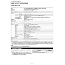
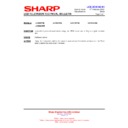
9. Remove the 1 lock screw
, 5 lock screws
, 2 lock screws
and detach the Main Shield
.
10.Remove the 2 lock screws
and 1 hook
and detach the Main PWB Unit
.
11.Remove the 2 lock screws
and detach the Mini AV PWB Unit
and Mini AV Cover
.
12.Remove the 2 lock screws
and 2 hooks
and detach the Power PWB Unit
.
13.Remove the 2 lock screws
and 4 hooks
and detach the Inverter PWB Unit
and Barrier Sheet
.
16
17
18
19
20
21
22
23
24
25
26
27
28
29
30
31
32
16
18
19
20
32
28
26
29
30
27
17
Main Shield
22
23
25
Main PWB Unit
24
Mini AV PWB Unit
Mini AV Cover
Power PWB Unit
31 Inverter PWB Unit
Barrier Sheet
21
LC-37D44E/S/RU-BK/GY
2 – 4
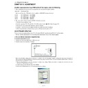
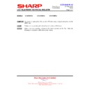
14.Remove the 1 lock screw
and detach the Bottom Cover
.
15.Remove the 4 lock screws
and detach the Stand Angle
.
16.Remove the 5 lock screws
and detach the Center Angle R
.
17.Remove the 5 lock screws
and detach the Center Angle L
.
18.Remove the 4 lock screws
, LCD Angle A
, LCD Angle B
from the LCD Panel Unit
.
33
34
35
36
37
38
39
40
41
42
43
44
42
44
42
43
43
37
38
35
39
Center Angle R
36 Stand Angle
Bottom
Cover
40
33
34
41
41
41
41
Center Angle L
LCD Angle A
LCD Panel Unit
LCD Angle A
LCD Angle B
LCD Angle B

