Read Sharp LC-20B6E (serv.man7) Service Manual online
15
LC-20B6E
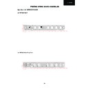
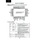
Precautions in servicing the B side (backside) of the main PWB unit
Precautions in servicing the B side (backside) of the main PWB unit
1. Disconnect the FFC between the main PWB (SC2001) and the analog PWB (SC3401), and then connect the
service-specific extension FFC (flat cable) (QCNW-C459WJQZ).
2. Disconnect the SC701 side of the lead from between the main PWB (SC701) and the analog PWB (P3704), and
then connect the service-specific extension cord (QCNW-B461WJQZ).
3. Disconnect the FFC for connection between the main PWB (SC1201) and LCD panel unit, and then connect the
service-specific extension FFC (flat cable) (QCNW-C458WJQZ).
4. Remove the lock screws from the main PWB, detach the PWB from the chassis frame, and then turn it over to
service.
Step
Part No.
Description
1
QCNW-C459WJQZ
Extension Cable 60-pin Main (SC2001)-Analog (SC340
1)
2
QCNW-C461WJQZ
Extension Cable 15-pin Main (SC701)-Analog (P3704)
3
QCNW-C458WJQZ
Extension Cable 80-pin Main (SC1201)-LCD Panel
CN1
SC1201
SC701
SC3401
SC2001
P3704
Main PWB
Main PWB
(Side-B)
(Side-B)
Inverter PWB
3
1
2
4
Analog PWB

