Read Sharp MX-RB12 (serv.man4) Service Manual online
MX-7040N MX-RB13 (RELAY UNIT) 18 – 3
2)
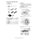
Connect the relay unit to the inserter.
Insert the pin in the inserter side into the hole in the relay unit.
Insert the pin in the inserter side into the hole in the relay unit.
Photo viewed from the R side
3)
Push up the lock lever to fix the relay unit and the inserter, and
use the removed screw to fix the lock lever.
use the removed screw to fix the lock lever.
MEMO: If they cannot be locked, follow the installing proce-
dures (height adjustment) of the complex machine and options
to adjust the height.
dures (height adjustment) of the complex machine and options
to adjust the height.
H. Height and tilt adjustment
NOTE: When the adjuster bolt is turned counterclockwise, the
height is decreased. When turned clockwise, the height is
increased.
increased.
NOTE: For the height and tilt adjustment, use the three adjuster
bolts under the unit.
Turn the adjustment nuts of the casters with a wrench in the arrow
direction to adjust the height. (When turning the adjustment nut one
rotation, the height of the relay unit is changed by about 1.75mm.)
direction to adjust the height. (When turning the adjustment nut one
rotation, the height of the relay unit is changed by about 1.75mm.)
• To increase the relay unit height, turn the nut in the direction [A].
• To decrease the relay unit height, turn the nut in the direction [B].
NOTE: Use the wrench attached to the finisher.
1)
Adjust the adjuster bolt (1) so that the difference in heights in
the front side the relay unit and the connection unit is within
2mm.
the front side the relay unit and the connection unit is within
2mm.
2)
Adjust the adjuster bolt (1) so that the difference in heights in
the rear side the relay unit and the connection unit is within
2mm.
the rear side the relay unit and the connection unit is within
2mm.
3)
Use adjuster bolt (3) so that the clearance between the
machine and the unit becomes uniform.
machine and the unit becomes uniform.
Ԙ
Ԛ
ԙ

