Read Sharp CD-XP300 (serv.man15) Service Manual online
CD-XP300H
– 38 –
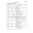
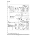
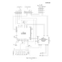
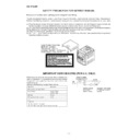
Figure 38 WIRING SIDE OF P.W.BOARD (7/7)
A
B
C
D
E
F
G
H
1
2
3
4
5
6
B C E
E C B
C N S 7 0 5
C N S 8 0 1
F R O M D I S P L A Y P W B
P 3 4 1 - F
F R O M M A I N P W B
P 3 2 2 - A
P 3 2 2 - A
T.F.
AC POWER
SUPPLY CORD
AC 230 V, 50 Hz
SUPPLY CORD
AC 230 V, 50 Hz
K801
K802
When Servicing, pay attention as the area
enclosed by this line ( ) is directly
connected with AC main voltage.
enclosed by this line ( ) is directly
connected with AC main voltage.
L841
D846
FW804
1
4
RL841
C844
PT841
SUB
POWER
TRANSFORMER
C841
R842
R841
D842
D845
D844
D843
R843
Q841
C843
C842
FW804
D806
ZD803
C804
R806
Q801
R808
D805
C802
C801
ZD802
C803
D803
C807
R802
R803
C806
R801
D804
R805
R804
ZD801
C805
CNP801
CNP802
11 10 9 8 7 6 5 4 3 2 1
5 4 3 2 1
D801
D802
C808
C809
PT801
MAIN POWER
TRANSFORMER
MAIN POWER
TRANSFORMER
F805
T2.5A L 250V
F801
T4A L 250V
F802
T4A L 250V
F803
T2A L 250V
T2A L 250V
F804
T2A L 250V
POWER PWB-A2
TRANSFORMER PWB-A3
1
4
C810
C811
HLD804B
HLD804A

