Read Sharp AR-LC4 (serv.man5) Service Manual online
AR-LC4 DISASSEMBLY AND REPLACEMENT/ADJUSTMENT 4 - 1
4. DISASSEMBLY AND
REPLACEMENT/ADJUSTMENT
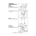
4. 1 Covers
[A] Front cover
(1) Pull out the drawer.
(2) Remove 4 screws and take off the front cover.
Note:
When installing the front cover, fit the arm on
the latch lever.
[C] Upper cover
(1) Pull out the drawer.
(2) Remove the rear cover.
(3) Loosen 4 screws and take off the upper cover.
[B] Rear cover
(1) Remove 4 screws and take off the rear cover.
Arm
Front cover
Rear cover
Upper cover
AR-LC4 DISASSEMBLY AND REPLACEMENT/ADJUSTMENT 4 - 2
[D] Right cover
(1) Remove 2 screws and take off the right cover
sliding it toward the front side.
4. 2 Tray Unit
(1) Pull out the drawer.
(2) Remove 1 screw and take off the stopper.
(3) Remove 4 screws (2 for the left side and 2 for
the right side) and take off the tray unit pulling it
upward.
Stopper
Left side
Right side
Right cover
AR-LC4 DISASSEMBLY AND REPLACEMENT/ADJUSTMENT 4 - 3
4. 3 Feed Unit
(1) Remove the upper cover.
(2) Remove the lever.
(4) Remove 3 screws for each at the front and rear
sides and take off the feed unit upward.
Lever
Connector
Front side
Rear side
(3) Disconnect 2 connectors (for tray motor, PC
board).
Feed unit
AR-LC4 DISASSEMBLY AND REPLACEMENT/ADJUSTMENT 4 - 4
4. 4 Electric Parts
[A] PC board
(1) Remove the rear cover.
(2) Disconnect 4 connectors and remove 1 screw
to take off the PC board.
[C] Transport motor
(1) Remove the upper cover.
(2) Disconnect 1 connector and remove 2 screws
to take off the transport motor.
[B] Tray motor
(1) Remove the rear cover.
(2) Disconnect 1 connector and remove 3 screws
to take off the tray motor.
[D] Tray sensor
(1) Remove the rear cover.
(2) Disconnect 1 connector and take off the tray
sensor.
Connector
Connector
Tray sensor

