Read Sony KDL-32S2000 / KDL-40S2000 Service Manual online
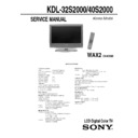
SERVICE MANUAL
SPECIFICATIONS
WAX2
CHASSIS
KDL-32S2000/40S2000
LCD Digital Color TV
Korea Model
Television system:
NTSC
American TV Standard
ATSC (8VSB terrestrial) ATSC compliant 8VSB
QAM on cable
QAM on cable
ANSI/SCTE 07 2000
Channel coverage:
Terrestrial (analog)
2-69
Cable TV (analog)
1-125
Terrestrial (digital)
2-69
Cable TV (digital)
1-135
Antenna:
75-ohm external terminal for VHF/UHF
Screen size (measured diagonally):
KDL-32S2000: 32 inches
KDL-40S2000: 40 inches
KDL-40S2000: 40 inches
Panel System:
LCD (Liquid Crystal Display) Panel
Display resolution (horizontal
× vertical):
1,366 dots
× 768 lines
VIDEO IN 1/2/3:
S VIDEO (4-pin mini DIN) (VIDEO 1/2 only):
Y: 1.0 Vp-p, 75 ohms unbalanced, sync negative
C: 0.286 Vp-p (Burst signal), 75ohms
C: 0.286 Vp-p (Burst signal), 75ohms
VIDEO:
1.0 Vp-p, 75 ohms unbalanced, sync negative
AUDIO:
500 mVrms (100% modulation)
Impedance: 47 kilohms
Impedance: 47 kilohms
HD/DVD IN 4/5:
Y P
B
P
R
(Component Video):
Y: 1.0 Vp-p, 75 ohms unbalanced, sync negative
P
P
B
: 0.7 Vp-p, 75 ohms
P
R
: 0.7 Vp-p, 75 ohms
Signal format: 480i, 480p, 720p, 1080i
AUDIO:
500 mVrms (100% modulation)
Impedance: 47 kilohms
Impedance: 47 kilohms
HDMI IN 6:
HDMI:
Video: 480i, 480p, 720p, 1080i
Audio: Two channel linear PCM 32, 44.1 and
Audio: Two channel linear PCM 32, 44.1 and
48 kHz, 16, 20 and 24bits
AUDIO:
500 mVrms (100% modulation)
Impedance: 47 kilohms
Impedance: 47 kilohms
AUDIO OUT:
500 mVrms (100% modulation)
More than 1 Vrms at the maximum volume setting (Variable)
More than 500 mVrms (Fixed)
More than 1 Vrms at the maximum volume setting (Variable)
More than 500 mVrms (Fixed)
PC IN 7:
D-sub 15-pin, analog RGB, 0.7 Vp-p, 75 ohms, positive
PC AUDIO INPUT:
Stereo mini jack, 0.5 Vrms, 1 kilohm
Headphones:
Stereo mini jack
Impedance: 16 ohms
Impedance: 16 ohms
Speaker:
Full range: KDL-32S2000: 42
× 150 mm (2)
KDL-40S2000
: 55 × 150 mm (2)
Speaker output:
10 W + 10 W
KDL-32/40S2000 (K) 2
Power requirement:
220 V AC, 60 Hz
Power consumption:
In use:
KDL-32S2000: 150 W
KDL-40S2000: 200 W
In standby:
Less than 0.25 W
Dimensions (W/H/D):
KDL-32S2000: (with stand) 792
× 593 × 219 mm
(without stand) 792
× 546 × 99 mm
KDL-40S2000: (with stand) 988
× 716 × 334 mm
(without stand) 988
× 664 × 103 mm
Mass:
KDL-32S2000: (with stand) 17 kg
(without stand) 15 kg
KDL-40S2000: (with stand) 27 kg
(without stand) 21 kg
Supplied accessories:
Remote control RM-YD005 (1)
Size AA batteries (2)
75-ohm coaxial cable (1)
AC power cord (1)
HD15-HD15 cable (1)
Support belt (1), securing screw (1) and wood screw (1)
Cable holder (1)
Operating Instructions (1)
Quick Setup Guide (1)
Leaflet (Installing the Wall-Mount Bracket, KDL-32S2000 only) (1)
Warranty Card (1)
Size AA batteries (2)
75-ohm coaxial cable (1)
AC power cord (1)
HD15-HD15 cable (1)
Support belt (1), securing screw (1) and wood screw (1)
Cable holder (1)
Operating Instructions (1)
Quick Setup Guide (1)
Leaflet (Installing the Wall-Mount Bracket, KDL-32S2000 only) (1)
Warranty Card (1)
Optional accessories:
Headphones plug adapter
Connecting cables
Wall-Mount Bracket: SU-WL31 (KDL-32S2000)
Connecting cables
Wall-Mount Bracket: SU-WL31 (KDL-32S2000)
SU-WL51 (KDL-40S2000)
Design and specifications are subject to change
without notice.
without notice.
Optional accessories’ availability
depends on its stock.
depends on its stock.
KDL-32/40S2000 (K) 3
SAFETY-RELATED COMPONENT WARNING
There are critical components used in LCD color TVs that are important for safety. These components are identified with shading
and
and
mark on the schematic diagrams and the electrical parts list. It is essential that these critical parts be replaced only with the
part number specified in the electrical parts list to prevent electric shock, fire, or other hazard.
NOTE: Do not modify the original design without obtaining written permission from the manufacturer or you will void the original
parts and labor guarantee.
USE CAUTION WHEN HANDLING THE LCD PANEL
When repairing the LCD panel, be sure you are grounded by using a wrist band.
When installing the LCD panel on a wall, the LCD panel must be secured using the 4 mounting holes on the rear cover.
To avoid damaging the LCD panel:
do not press on the panel or frame edge to avoid the risk of electric shock.
→
→
do not scratch or press on the panel with any sharp objects.
→
→ avoid contact with water. It may cause a short circuit within the module.
→ disconnect the AC adapter when replacing the backlight (CCFL) or inverter circuit.
→ disconnect the AC adapter when replacing the backlight (CCFL) or inverter circuit.
(High voltage occurs at the inverter circuit at 650Vrms.)
→ always clean the LCD panel with a soft cloth material.
→ protect the panel from ESD to avoid damaging the electronic circuit (C-MOS).
LEAKAGE CURRENT HOT CHECK CIRCUIT
AC Volt-meter
1.5 Kohm/10W
To Instruments
exposed
METALLIC PARTS
exposed
METALLIC PARTS
Good Earth Ground
such as WATER PIPE,
CONDUIT etc.
such as WATER PIPE,
CONDUIT etc.
!
KDL-32/40S2000 (K) 4
example 1
It is strongly recommended to use Lead Free Solder material in order to guarantee optimal
ii
quality of new solder joints.
q
q
Lead Free Solder is available under the following part numbers:
Due to the higher melting point of Lead Free Solder the soldering iron tip temperature needs to be set to 370 degrees centigrade.
This requires soldering equipment capable of accurate temperature control coupled with a good heat recovery characteristics.
This requires soldering equipment capable of accurate temperature control coupled with a good heat recovery characteristics.
For more information on the use of Lead Free Solder, please refer to http://www.sony-training.com
h
h
Part number
Diameter
Remarks
0.3mm
0.25Kg
0.50Kg
0.5mm
0.4mm
0.50Kg
0.6mm
0.25Kg
0.8mm
1.00Kg
1.0mm
1.00Kg
1.2mm
1.00Kg
1.6mm
1.00Kg
Lead Free Solder. The boards are identified by the LF logo located
ll
servicing of these boards requires special precautions to be taken as
outlined below.
outlined below.

