Read Sharp VC-M303 (serv.man10) Service Manual online
31
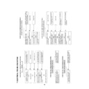
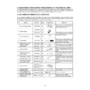
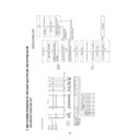
Measuring
instrument
instrument
Mode
Test point
Colour TV monitor
DV voltmeter
DV voltmeter
RF signal at E12-CH(by VHF
signal generator)
signal generator)
Pin(2)(Sig.) of P1501.
Pin(4)(GND.) of P1501.
Pin(4)(GND.) of P1501.
Control
R1626 RF AGC control
Specification
4.3
±0.2V(G/S Hi-Fi models)
1.Receive the E12 channel signal(colour bar signal at
87.5% modulated.) at input field strength: 56dBV of
antenna terminal.
2.Connect a DC voltmeter to test point shown in table.
3.Look the voltmerter and adjust R1626 so that the
voltage be specified.
87.5% modulated.) at input field strength: 56dBV of
antenna terminal.
2.Connect a DC voltmeter to test point shown in table.
3.Look the voltmerter and adjust R1626 so that the
voltage be specified.
Measuring
instrument
instrument
Mode
Test point
Colour TV monitor
DV voltmeter
DV voltmeter
Control
T1601 VCO control
Specification
2.5
±0.2V
RF signal at E12-CH(by VHF
signal generator)
signal generator)
Pin(1)(Sig.) of P1501.
Pin(4)(GND.) of P1501.
Pin(4)(GND.) of P1501.
ADJUSTMENT OF RF AGC ADJUSTMENT
1.Receive the E12 channel signal(colour bar signal at
87.5% modulated.) at input field strength: 56dBV of
antenna terminal.
2.Connect a DC voltmeter to test point shown in table.
3.Look the voltmerter and adjust T1601 so that the
voltage be specified.
87.5% modulated.) at input field strength: 56dBV of
antenna terminal.
2.Connect a DC voltmeter to test point shown in table.
3.Look the voltmerter and adjust T1601 so that the
voltage be specified.
ADJUSTMENT OF VCO CIRCUIT


