Read Sharp DV-5101H (serv.man21) Technical Bulletin online
Sharp Electronics (UK) Limited
Originator AJ Supervisor Approval Date / / Reference TRS-036
Revision
White – Carry out as required, Yellow – Carry out as required and whenever the unit comes in for service, Red – Carry out on all units
DV5101-001
Month of Issue:
Classification: Routine
TELEVISION TECHNICAL BULLETIN
Page 1 of 1
MODELS
DV5101H
DV5103H
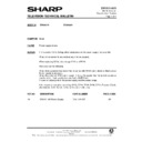
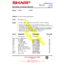
SYMPTOM Dead.
CAUSE
Power supply failure.
ACTION
In the event of Q702 failing, other components in the power supply may also fail.
Check all components and replace any that are suspect.
When replacing Q702, also change C710 and R716.
Also carry out the following.
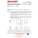
Check that a posistor has been fitted in series with R705 and a diode is fitted across
R716 ( anode to chassis ).
Check the value of R719 out of circuit. If it is a 1k resistor then fit an 2k2 resistor in
parellel with it. Later production sets had a 680R fitted.
Inspect all solder joints in the power supply and line output stage.
R716 ( anode to chassis ).
Check the value of R719 out of circuit. If it is a 1k resistor then fit an 2k2 resistor in
parellel with it. Later production sets had a 680R fitted.
Inspect all solder joints in the power supply and line output stage.
A kit of parts is avialable containing Q702, C710, R716, D706, D711, Posistor, Diode,
2k2 resistor, D754, IC700, IC750, Q700, Q701 and L702.
2k2 resistor, D754, IC700, IC750, Q700, Q701 and L702.
REF NO
DESCRIPTION
PART NUMBER
PRICE CODE
Kit
DV5101/3H Power Supply
DV5101H-KIT
AM
Display

