Read Sharp DV-5101H (serv.man17) Technical Bulletin online
CTV2001 03 05
Month of Issue:
March 2001
Classification:
White
TELEVISION TECHNICAL BULLETIN
Page 1 of 1
Sharp Electronics (UK) Limited
Reference AVW12032001-1
Revision 1
White – Carry out as required
Yellow – Carry out as required and whenever the unit comes in for service
Red – Carry out on all units
MODELS
DV5101H
DV5103H
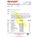
SYMPTOM Repeated or intermittent failures of the chopper power supply transistor (Q702).
ACTION
In some cases, it is possible for the power supply to fail repeatedly due to incorrect
drive conditions applied to Q702. To assist in finding faults in this area, it is possible
to run the oscillator within IC700 using an external DC power supply.
drive conditions applied to Q702. To assist in finding faults in this area, it is possible
to run the oscillator within IC700 using an external DC power supply.
With the mains supply disconnected, supply pin 9 of IC700 with 12VDC, ensure that
the 0V line of the power supply is connected to the negative plate of the main
smoothing capacitor, C705.
the 0V line of the power supply is connected to the negative plate of the main
smoothing capacitor, C705.
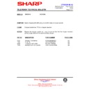
When the power supply is turned on, the following waveforms should be present.
Note the relative DC levels, if these are incorrect, then the chopper transistor will be
incorrectly biased and may fail prematurely.
Note the relative DC levels, if these are incorrect, then the chopper transistor will be
incorrectly biased and may fail prematurely.
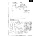
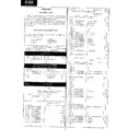
Figure 1: Waveforms present when IC700 is connected to an External Power Supply
Note that all the above waveforms are approximate; there may be slight variations between chassis.
1.5V
4.8V
20uS
12uS
0V
1V
0V
800mV
700mV
3.0V
Pin 8
of
IC700
Base
of
Q702
Display

