Read Sharp LL-T2010W (serv.man2) Service Manual online
LL-T2010W
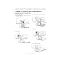
OUTLINE OF THE PRODUCT, NOMENCLATURE AND FUNCTION
1 – 4
■
■
■
■
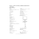
PRODUCT DESCRIPTION
1. INPUT button
To switch between the signal's input terminals. (Analog RGB input ter-
minal
minal
13
DVI-I input terminal)
2. MENU button
This button is used to pop-up, select and close the OSD Menu.
3. SELECT button
This button is used to select menu options when the OSD Menu is dis-
played.
4.
e d
buttons
When the On Screen Display (OSD) Menu is displayed:
These buttons are used to increase or decrease the value of a selected
option.
option.
When the OSD Menu is not displayed:
These buttons are used to adjust backlight brightness.
5. Power LED
This LED is lit green when in use and orange when in power-saving
mode.
mode.
6. Power button
Pressing this button turns the power on. (After turning the power on, it
may take a little time before the screen displays.)
Press the button again to turn the power off.
7. Analog RGB input terminal
Remove the cover to see the analog RGB input terminal. At the time of
leaving the factory the analog signal cable is connected.
8. Power terminal
Remove the cover to see the power terminal. The AC adapter is con-
nected here.
nected here.
9. Security lock anchor
By connecting a security lock (commercially available) to the security
lock anchor, the monitor is fixed so that it cannot be transported.
The security slot works in conjunction with Kensington Micro Saver
Security Systems.
10. Analog signal cable
Connects to the computer's analog RGB output terminal.
11. USB port
Remove the cover to see the USB port (upstream: 1 port, downstream:
2 ports).
12. DVI-I input terminal
Remove the cover to locate the DVI-I input terminal (DVI-I29 pin).
The computer's digital RGB output terminal or analog RGB output ter-
minal can be connected here.
For a digital signal input: It can be connected to a computer with a DVI-
compatible output terminal (DVI-D24 pin or DVI-I29 pin) and which has
UXGA output ability. Depending on the computer to be connected, cor-
UXGA output ability. Depending on the computer to be connected, cor-
rect display may or may not be possible.
To be able to connect, a cable that is to be purchased separately is
required.
To connect to a digital RGB output terminal: Digital signal cable (model
name: NL-C01E)
name: NL-C01E)
To connect to an analog RGB output terminal: Analog signal cable
(model name: NL-C02E)
(model name: NL-C02E)
13. Ventilation openings
Note: Never block the ventilation openings as this may lead to over-
heating inside the monitor and result in malfunction.
Adjusting the angle of the monitor
Lightly holding both sides of the monitor, adjust it to a suitable viewing
angle.
Caution: Pressure from hands on the LCD panel could cause damage.
1
Front view
Rear view
2 3
4
5 6
9
7
8
13
13
13
10
12
11
approx.30
approx.45
approx.45
approx.5

