Read Sharp LL-T2010W (serv.man14) Service Manual online
LL-T2010W
DISASSEMBLY AND ASSEMBLY
3 – 1
CHAPTER 3. DISASSEMBLY AND ASSEMBLY
A
A
C
C
D
E
E
F
F
D
B
B
1
1
2
5
7
9
10
11
2
3
4
1
1
3
7
28
30
30
32
32
32
33
34
35
7
7
7
8
6
9
10
11
17
18
18
22
24
27
23
24
23
16
28
28
29
30
30
31
28
28
20
14
15
3
4
1
1
6
6
8
12
5
13
13
19
19
21
25
25
26
21
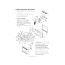
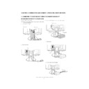
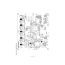
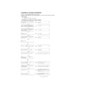
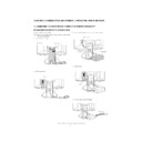
1. SEPARATION OF DISPLAY SECTION AND STAND SECTION
1) Remove inlet cover
1
and D-sub cover
2
.
2) Remove stand cover
3
.
3) Remove two screws
4
, and remove tilt cover section
5
.
4) Remove four screws
6
, and separate stand section
7
and display section
G
.
5) Remove two screws
8
, and remove support angle
9
.
6) Remove VGA cable
F
from display section
G
.
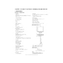
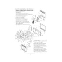
2. LCD MODULE DISASSEMBLY
1) Remove nine screws
1
, and remove display cover
2
.
2) Remove three screws
3
, and remove VASE plate
4
.
3) Remove three screws
5
, and remove USB PWB
6
.
4) Remove seven screws
7
, and remove shield cover plate
8
.
5) Remove KEY cable
9
, power cable
F
, and inverter control
cable
G
from interface PWB
J
.
6) Remove four hex screws
H
and eight screws
I
, and remove
interface PWB
J
.
7) Remove cable process sheet
K
, and remove LCD cable
A
L
and LCD cable B
M
.
8) Remove power cable
F
, inverter control cable
G
, and
inverter cable
N
from DC jack PWB
P
.
9) Remove six screws
O
, and remove DC jack PWB
P
.
10) Remove inverter cable
N
from inverter PWB
W
.
11) Remove six screws
Q
, and remove inverter shield
R
.
12) Remove two screws
S
, and remove connector discon-
nection preventing sheet
T
.
13) Disconnect connector
U
at six positions.
14) Remove two screws
V
, and remove inverter PWB
W
.
15) Remove six screws
X
, and remove LCD shield plate
Y
.
16) Remove six screws
Z
, and remove display mask
[
.
17) Remove four screws
\
from LCD module
_
, and remove
LCD angle R
]
and LCD angle L
^
.
Display

