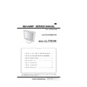
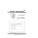
Read Sharp LL-T1810A (serv.man4) Service Manual online
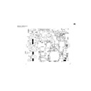
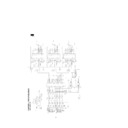
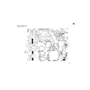
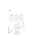
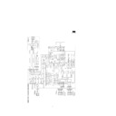
3. Wiring diagram
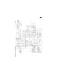
This drawing shows a basic circuit. The actual wiring might be somewhat different from this drawing.
•
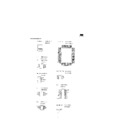
Circuit diagram (Main PWB, Control PWB, Jack PWB, D-sub PWB)
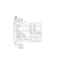
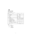
1. Resistance indications
[Resistance]
•
Unit :
No indication - - - - -
Ω
, k - - - - - k
Ω
, M - - - - - M
Ω
•
Error :
No indication, J - - - - - 5%, D , F- - - - - 1%
•
Rated power : No indication - - - - - 1/16W, (2125) - - - - - 1/10W, (3225) - - - - - 1/4W, (5025) - - - - - 1W
Type
Resistance
Carbon tact film resistance
Volume resistance
2. Capacitor indications
[Capacitor]
Aluminium electrolytic capacitor
•
Unit :
F - - - - - F, PF - - - - - PF
•
Rated voltage : /10V - - - - - 10V, /16V - - - - - 16V, /25V - - - - - 25V, /35V - - - - - 35V, /50V - - - - - 50V
Ceramic capacitor
•
Unit :
F - - - - - F, PF - - - - - PF
•
Temperature characteristic :
No indication - - - - - +30%, -80% (B) - - - - - 10%, (CH) - - - - - 0%
•
Rated voltage :
No indication - - - - - 50V, (16V) - - - - - 16V, (25V) - - - - - 25V
Type
Capacitor
Ceramic capacitor
Non-polarity aluminium electrolytic
capacitor
Non-polarity aluminium electrolytic
capacitor
Aluminium electrolytic capacitor
3. Test land indication
( )
( )
Test lands (LD ) do not have pins attached.

