Read Sharp DV-L70 (serv.man3) Service Manual online
19
DV-L70S
DV-L70BL
DV-L70W
NO
Is a signal being inputted to the following, each
output terminal of the integrated circuit?
IC6000 3pin AUDIO(L-CH)-SIG.
IC6000 5pin AUDIO(R-CH)-SIG.
Set the disc on the disc tray.
It confirms that there is no problem by flowchart
NO.12.
YES
The control signal line of IN_H is checked.
NO
Check the line between the pins 16, 13 of IC801
and pins 3, 5 of IC6000.
YES
YES
The control peripheral circuit of IN_H is examined
in each of 9 of IC6203 and IC6202, the 10 pin.
YES
The control signal line of SMUT is checked.
NO
Is a signal being inputted to the following, each
output terminal of the integrated circuit?
IC6203 2, 5pin AUDIO(L-CH)-SIG.
IC6202 5pin AUDIO(R-CH)-SIG.
YES
Check the line between the pins 1, 7 of IC6000 and
pins 2, 5 of IC6203 and IC6202.
NO
Does a signal come out in the following, each
output terminal of the integrated circuit?
IC6203 2, 5pin AUDIO(L-CH)-SIG.
IC6202 4pin AUDIO(R-CH)-SIG.
YES
Is the control signal of IN_H added to each of 9 of
IC6203 and IC6202, the 10 pin?
NO
Is a signal being inputted to the following, each
output terminal of the integrated circuit?
IC6203 12pin AUDIO(L-CH)-SIG.
IC6202 12pin AUDIO(R-CH)-SIG.
YES
The line of the space to 12 pin of IC6203, IC6202 is
checked through sound volume (R6010) from 4 pin
of IC6203, IC6202.
NO
Is a signal being inputted to the following, each
output terminal of the integrated circuit?
IC6002 2pin AUDIO(L-CH)-SIG.
IC6002 6pin AUDIO(R-CH)-SIG.
The actuation of the audio mute circuit of Q2004,
Q2005, Q6615, Q6616 is checked.
YES
Sound do not oper
ate nor
mally
.
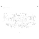
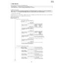
FLOW CHART NO.19
YES
YES
YES
NO
NO
NO
Is the PDP signal of 38 pin of IC1101 normal?
Is the synchronizing signal of 7 pin of IC1101
normal?
YES
YES
Is a synchronizing signal being inputted to 36 pin of
IC1801?
Is a synchronizing signal being outputted to 3 pin
of IC1900?
NO
Check the betweenthe emmiter and pin 36 of IC1801.
Check the pins 38, 44, 43 of IC1101 and pins
L1109, D1105, IC1102, Q1101, etc.
Check the peripheral circuit pins 71, 70 of IC1101,
C1122 and R1103 (image plane center position).
Is the horizontal position of the picture image
normal?
YES
The readjustment of R1103 (SCREEN. CENTER
POS.) is done.
SYNC SEPA. (IC1900), Q1900 and MONO MULTI
(IC1901), IC1902, IC1801 are checked.
The synchronism of the picture image can't be tak
en.
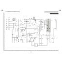
FLOW CHART NO.18
Replace the IC1900.
Check the LCD panel unit.
The headphone audio output is not emitted.
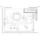
FLOW CHART NO.21
Check or replace IC6002 (AUDIO POWER OUT)
and IC6601 (POWER REG.)
The control signal line of SMUT is checked.
The control signal line of IN_H is checked.
NO
YES
The control peripheral circuit of IN_H is examined
in each of 9 of IC6203 and IC6202, the 10 pin.
Is the control signal of IN_H added to each of 9 of
IC6203 and IC6202, the 10 pin?
NO
YES
YES
Check or replace speaker.
YES
Check the outside output terminal (J6000).
YES
Check the headphone output terminal (J6001).
YES
Does a signal come out in the following, each
output terminal of the integrated circuit?
IC6002 16, 13pin AUDIO(L-CH)-SIG.
IC6002 12, 9pin AUDIO(R-CH)-SIG.
NO
NO
Does a signal come out in the following, each
output terminal of the integrated circuit?
IC6203 3, 15pin AUDIO(L-CH)-SIG.
IC6202 3, 15pin AUDIO(R-CH)-SIG.
Check the periphery circuit of IC6602.
NO
Does a signal come out in the following, each
output terminal of the integrated circuit?
IC6602 1pin AUDIO(L-CH)-SIG.
IC6602 7pin AUDIO(R-CH)-SIG.
The outside output audio doesn't come out.
(Speak
er audio comes out.)
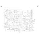
FLOW CHART NO.20
The actuation of the audio mute circuit of Q2004,
Q2005, Q6615, Q6616 is checked.
The control signal line of SMUT is checked.
NO
The actuation of the audio mute circuit of Q2004,
Q2005, Q6012, Q6013 is checked.

