Read Sharp SD-AT100 (serv.man9) Technical Bulletin online
AUD 2005 01 01
Date of Issue: 10
th
January 2005
Classification:
White
AUDIO TECHNICAL BULLETIN
Page 2 of 2
Sharp Electronics (UK) Limited
Reference – AvW 10 01 2005 - 1
Revision - 1
White – Carry out as required
Yellow – Carry out as required and whenever the unit comes in for service
Red – Carry out on all units
ACTION
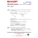
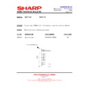
Re-flow the solder on connector BEI05A as shown in the pictures on page 1.
unit. Follow the steps outlined below:-
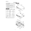
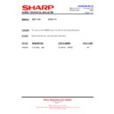
2. Remove the top and side covers – the top cover as shown in figure 1.
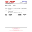
3. Remove the rear panel as shown in figure 2.
4. Remove the screws that attach the bottom plate to the front panel.
5. It should now be possible to prise the two halves apart to gain access to the rear of
3. Remove the rear panel as shown in figure 2.
4. Remove the screws that attach the bottom plate to the front panel.
5. It should now be possible to prise the two halves apart to gain access to the rear of
the Display Panel.
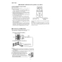
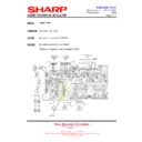
6. Remove the one screw holding in the protective plastic sheet in place. Refer to
figure 3
7. When joint has been re-flowed, reverse the above procedure to re-assemble.
Figure 1
Figure 2
Figure 3
Remove this screw
so that the protective
sheet can be moved.
so that the protective
sheet can be moved.
Display

