Read Sharp CD-E250 (serv.man9) Service Manual online
– 11 –
CD-E250E
CD-E550E
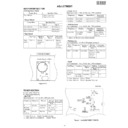
ADJUSTMENT
MECHANISM SECTION
•••••
Driving Force Check
Torque Meter
Specified Value
Play: DM-300
Tape 1: Over 80 g
Tape 2: Over 80 g
Tape 2: Over 80 g
•••••
Torque Check
Torque Meter
Tape 2
Play: DM-300
10 to 20 g.cm
10 to 20 g.cm
Fast forward: DM-300
—
Over 50 g.cm
Rewind: DM-300
—
Over 50 g.cm
Specified Value
Tape 1
Specified
Value
Adjusting
Point
Instrument
Connection
Test Tape
Tape
TCC-119
Variable
3,000
±
30 Hz
Speaker
speed
Resistor in
Terminal
motor.
(Load
resistance:
6 ohms)
resistance:
6 ohms)
•••••
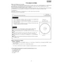
Tape Speed
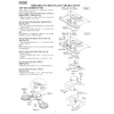
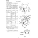
Figure 11-1
Tape
Motor
Motor
Variable Resistor in Motor
TAPE MECHANISM
FM IF
FM RF
VR351
FM MUTE
Level
Level
T351
AM IF
T302
T306
T304
IC301
IC302
L303
L302
CNP301
FM BAND
COVERAGE fL
COVERAGE fL
AM BAND
COVERAGE fL
COVERAGE fL
AM TRACKING
fL
fL
MAIN PWB
1
1
11
12
22
20
R381
R356
R357
TP301
TP302
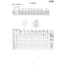
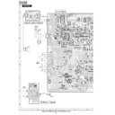
Figure 11-2 ADJUSTMENT POINTS
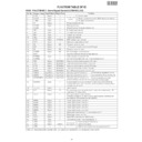
TUNER SECTION
Frequency
Frequency
Display
Setting/
Adjusting
Parts
Instrument
Connection
IF
450 kHz
1,620 kHz
T351
*1
AM Band
—
522 kHz
(fL): T306
*2
Coverage
1.1
±
0.1 V
AM
990 kHz
990 kHz
T302
*1
Tracking
fL: Low-range frequency
fH: High-range frequency
fH: High-range frequency
Signal generator: 400 Hz, 30%, AM modulated
• AM IF/RF
*1. Input: Antenna
Output: Speaker terminal
*2. Input: Input is not connected
Output: TP301
Adjusting
Parts
Instrument
Connection
Display
Frequency
98.00 MHz
98.00 MHz
VR351*1
Input: CNP301
(30 dB
µ
V)
Output: Speaker
Terminal
Terminal
• FM Mute Level
Signal generator: 1 kHz, 40 kHz dev., FM modulated
Signal generator: 1 kHz, 40 kHz dev., FM modulated
*1. Adjust so that an output signal appears.
• FM RF
Signal generator: 1 kHz, 75 kHz dev., FM modulated
Signal generator: 1 kHz, 75 kHz dev., FM modulated
FM Band
—
87.50 MHz
(fL): L303
*1
Coverage
3.4
±
0.1 V
FM RF
98.00 MHz
98.00 MHz
L302
*2
(10~30 dB)
Test Stage
Frequency
Frequency
Display
Setting/
Adjusting
Parts
Instrument
Connection
*1. Input: Antenna,
Output: TP301
*2. Input: Antenna,
Output: Speaker Terminal
• FM Detection
Signal generator: 10.7 MHz, FM sweep generator
Signal generator: 10.7 MHz, FM sweep generator
FM IF
10.7 MHz
98.00 MHz
T304(Turn
Input: Pin 1 of
the core of
IC301
T304 fully
counter-
clockwise).
counter-
clockwise).
Test
Stage
Frequency
Frequency
Display
Setting/
Adjusting
Parts
Instrument
Connection
Check Point
Instrument
Connection
Display
Frequency
87.5 MHz
87.5 MHz
2.2 V
±
1.0 V
TP301
108 MHz
108 MHz
7.8 V
±
1.0 V
TP301
• Check FM VT
Signal generator: 1 kHz, 40 kHz dev., FM modulated
Signal generator: 1 kHz, 40 kHz dev., FM modulated
Display

