Read Sharp CD-E250 (serv.man8) Service Manual online
CD-E250E
CD-E550E
– 8 –
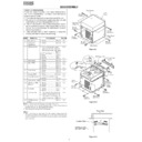
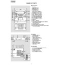
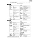
REMOVING AND REINSTALLING THE MAIN PARTS
TAPE MECHANISM SECTION
Perform steps 1 to 6 and 8 of the disassembly method to
remove the tape mechanism.
remove the tape mechanism.
Figure 8-1
Figure 8-2
Figure 8-3
Figure 8-4
Figure 8-5
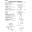
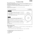
How to remove the record/playback and erase
heads (TAPE 1) (See Fig. 8-1)
heads (TAPE 1) (See Fig. 8-1)
1. When you remove the screws (A1) x 2 pcs., the record/
playback head can be removed.
How to remove the playback head (TAPE 2)
(See Fig. 8-2)
(See Fig. 8-2)
1. When you remove the screws (B1) x 2 pcs., the erase head
can be removed.
2. When you remove the screws (B2) x 2 pcs., the record/
playback head can be removed.
Note:
After replacing the heads and performing the azimuth
adjustment, be sure to apply screwlock.
After replacing the heads and performing the azimuth
adjustment, be sure to apply screwlock.
How to remove the pinch roller (TAPE 1,2)
(See Fig. 8-3)
(See Fig. 8-3)
1. When you remove the screw (C1) x 1 pc., the pinch roller
can be removed.
Note:
When installing the pinch roller, pay attention to the spring
mounting position.
When installing the pinch roller, pay attention to the spring
mounting position.
How to remove the motor (See Fig. 8-4)
1. Remove the belt.
2. Remove the screws (D1) x 4 pcs., to remove the motor
2. Remove the screws (D1) x 4 pcs., to remove the motor
bracket.
3. Remove the screws (D2) x 3 pcs., to remove the motor.
How to remove the belt (TAPE 1)
(See Fig. 8-5)
(See Fig. 8-5)
1. Remove the main belt (F1) x 1 pc., from the motor side.
How to remove the belt (TAPE 2)
(See Fig. 8-5)
(See Fig. 8-5)
1. Remove the main belt (G1) x 1 pc., from the motor side.
2. Remove the FF/REW belt (G2) x 1 pc.
2. Remove the FF/REW belt (G2) x 1 pc.
Record/
Playback Head
Playback Head
(A1)x1
ø2x3mm
ø2x3mm
(A1)x1
ø2x7mm
ø2x7mm
TAPE 1
Erase Head
Record/
Playback Head
Playback Head
(B1)x2
ø2x8mm
ø2x8mm
TAPE 2
(B2)x1
ø2x3mm
ø2x3mm
(B2)x1
ø2x7mm
ø2x7mm
TAPE 1
TAPE 2
<A>
Pinch Roller
(C1)x1
(C1)x1
Pinch Roller
Pawl
Pawl
(D1)x2
ø2x4mm
ø2x4mm
(D1)x3
Special Screw
Special Screw
Motor
Motor
Motor
Bracket
Bracket
Motor
Bracket
Bracket
(D1)x2
ø2x4mm
ø2x4mm
TAPE 2
TAPE 1
TAPE 2
Main Belt
(G1)x1
Main Belt
(G1)x1
TAPE 1
Main Belt
(F1)x1
Main Belt
(F1)x1
Motor
Motor
REW/FF
Clutch Ass'y
Clutch Ass'y
Main
Belt
(F1)x1
Belt
(F1)x1
Main
Belt
(G1)x1
Belt
(G1)x1
REW/FF
Belt
(G2)x1
Belt
(G2)x1
– 9 –
CD-E250E
CD-E550E
Figure 9-1
How to remove the flywheel (TAPE 1,2)
(See Fig. 9-1.)
(See Fig. 9-1.)
1. Remove the stop washer (H1) x 1 pc., with a small precision
screwdriver to extract the flywheel from the capstan metal.
Note:
When the stop washer is deformed or damaged, replace it
with a new one.
When the stop washer is deformed or damaged, replace it
with a new one.
How to reinstall the parts
Install each part in the reverse order of the removal with care.
TAPE 1
TAPE 2
Stop
Washer
Washer
Driver
(H1)x1
Stop Washer
Stop Washer
Mechanism
Chassis
Chassis
Washerx2
Flywheel
How to remove the tape mechanism PWB
(TAPE 1,2) (See Fig. 9-2.)
(TAPE 1,2) (See Fig. 9-2.)
1. Remove the screw (J1) x 1 pc., to remove the tape
mechanism PWB.
2. Remove the screw (J2) x 1 pc.
3. Remove the solder joints (J3) x 2 pcs., to remove the tape
3. Remove the solder joints (J3) x 2 pcs., to remove the tape
mechanism PWB.
Figure 9-2
TAPE 1,2
Tape
Mechanism
PWB
Mechanism
PWB
Tape
Mechanism
PWB
Mechanism
PWB
(J3)x2
Solder
Joint
Solder
Joint
(J2)x1
ø2x8mm
ø2x8mm
(J1)x1
ø2x3mm
ø2x3mm
CD-E250E
CD-E550E
– 10 –
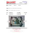
Figure 10-1
CD PLAYER SECTION
Perform steps 1, 2, 3, 10,11, and 12 of the disassembly
method to remove the CD mechanism.
method to remove the CD mechanism.
How to remove the T/T rotate motor
(See Figs. 10-1)
(See Figs. 10-1)
1. Remove the screws (A1) x 2 pcs.
2. Remove the belt (A2) x 1 pc.
3. Remove the screws (A3) x 2 pcs., to remove the T/T rotate
2. Remove the belt (A2) x 1 pc.
3. Remove the screws (A3) x 2 pcs., to remove the T/T rotate
motor.
(A1)x2
ø2.4x3mm
ø2.4x3mm
(A3)x2
ø3x10mm
ø3x10mm
(A2)x1
Loading Tray
(Bottom View)
(Bottom View)
Loading Tray
T/T Motor PWB
T/T Rotate Motor
(B1)x2
ø2.4x5mm
ø2.4x5mm
Up/Down Loading Motor
CD Player Unit
(B2)x1
Figure 10-2
How to remove the up/down loading motor
(See Figs. 10-2)
(See Figs. 10-2)
1. Remove the screws (B1) x 2 pcs.
2. Remove the belt (B2) x 1 pc.
2. Remove the belt (B2) x 1 pc.
How to remove the CD mechanism unit
(See Fig. 10-3)
(See Fig. 10-3)
Perform steps 1, 2, 3, 10and 13 of the disassembly method to
remove the CD mechanism.
1. Remove the screws (C1) x 4 pcs., to remove the mechanism
remove the CD mechanism.
1. Remove the screws (C1) x 4 pcs., to remove the mechanism
unit.
Note
After removing the connector for the optical pickup from the
connector wrap the conductive aluminium foil around the front
end of connector so as to protect the optical pickup from
electrostatic damage.
After removing the connector for the optical pickup from the
connector wrap the conductive aluminium foil around the front
end of connector so as to protect the optical pickup from
electrostatic damage.
Figure 10-3
Holder
CD Mechanism Unit
Holder
PWB
PWB
(C1)x4
ø2.5x10mm
ø2.5x10mm

