Read JBL FLIP 3 Service Manual online
Released Global Quality 201
Harman Consumer Group, Inc.
Rev 1.
8500 Balboa Boulevard
CONTENTS
2
3
3
6
7
7
Technical Specifications
Safety
Safety
s
e
t
o
N
&
g
n
i
n
r
a
W
,
n
o
i
t
c
u
r
t
s
n
I
Set
Diagram
Schematic Diagrams
PCB Layout Diagrams
PCB Layout Diagrams
Exploded view
Spare Parts List
Revision List
Revision List
./201
4
5
5
9
10
11
12
11
12
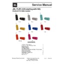
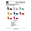
Service Manual
JBL FLIP3 (S/N starting with ND)
Bluetooth Portable Speaker
Black
Grey
Orange
Blue
Red
Yellow
Teal
Pink
8
Disassembly Instruction and Splash Proof process
Technical Specifications
1 Audio Section
1.1.1 Speaker Output
Description
Specification
Rated Output Power
2 x 8W +-10% (Measure before power limiter at 1% THD).
Please refer to Acoustic Design Specification.
Please refer to Acoustic Design Specification.
Input Sensitivity
Aux : 370mV +/- 10%
Wireless input:-9dBfs +/-1dB
Wireless input:-9dBfs +/-1dB
Input Overload
Aux : 1V rms
BT: 0dBFS
BT: 0dBFS
Auto Turn On Input Sensitivity
@1KHz, Typical : 2mV Limit : 4mV
@100Hz Typical : 10mV Limit :15mV
@100Hz Typical : 10mV Limit :15mV
Frequency Response (Output Power)
Aux_in : 40Hz to 20KHz +/- 1dB (EQ setting is disable)
BT: 20Hz to 19KHz +/- 1dB (EQ setting is disable)
BT: 20Hz to 19KHz +/- 1dB (EQ setting is disable)
Frequency Response (Output Power) with
EQ setting
EQ setting
TBC
THD+N at 1W
<0.5%@100hz/7khz, else<0.3%
THD+N at Rated Output Power
<1%
Signal-to-Noise ratio at Rated Output Power 80dB (A-Weighted)
Channel Separation
45dB @100Hz
50dB @1KHz
45dB @10KHz
50dB @1KHz
45dB @10KHz
Channel Crosstalk
80dB @100Hz
75dB @1KHz
70dB @10KHz
75dB @1KHz
70dB @10KHz
Inter Channel Gain Difference
<0.5dB
Residual Noise
80nW
2-1
1.1.2 Microphone
Short Circuit Protection at Output Stage
The amplifier should be protected so that no functional failure
occurs when it is operated with a short across its output stage
for 2 minutes. The amplifier should recover after removing the
short condition.
occurs when it is operated with a short across its output stage
for 2 minutes. The amplifier should recover after removing the
short condition.
DC Offset Protection
The amplifier with output power of higher than 50W per channel
must ensure that no DC is available at its output in normal mode
as well as abnormal/faulty condition mode.
must ensure that no DC is available at its output in normal mode
as well as abnormal/faulty condition mode.
Thermal Protection
There should not be any breakdown or activation of any
protection circuit during the entire thermal profile test. Refers to
the Thermal Profile test stated in Reliability Test Plan for
Multimedia Powered Speaker System.
protection circuit during the entire thermal profile test. Refers to
the Thermal Profile test stated in Reliability Test Plan for
Multimedia Powered Speaker System.
Output Power Duration
FTC requirement:
Warm-up or preconditioning period at 1/8 power for 1 hour,
followed by 5 minutes of continuous Rated Output Power (ROP).
Channels in the same frequency range are tested at ROP.
Subwoofer is tested separately.
Warm-up or preconditioning period at 1/8 power for 1 hour,
followed by 5 minutes of continuous Rated Output Power (ROP).
Channels in the same frequency range are tested at ROP.
Subwoofer is tested separately.
IEC requirement :
Output power distortion limited of 60 sec
Short-term maximum output power of 1 sec
Long-term maximum output power of 1 minutes
Temperature-limited output power infinitely
Output power distortion limited of 60 sec
Short-term maximum output power of 1 sec
Long-term maximum output power of 1 minutes
Temperature-limited output power infinitely
1.2 USB Section
Reference : USB-IF USB 2.0 Electrical Test Specification Version 1.03 dated January, 2005
2-2
1.3 Bluetooth Section
1.3.1 General
Description
Specification
Bluetooth Standard
Version 4.1
Frequency Band
2.402 – 2.480 GHz
Host Interface
UART
Profile Supported
HFP (Audio Gateway and Handsfree)
A2DP (Advanced Audio Distribution Profile)
AVRCP (Audio/Video Remote Control Profile)
Refer SRD
A2DP (Advanced Audio Distribution Profile)
AVRCP (Audio/Video Remote Control Profile)
Refer SRD
Audio Codec
SBC (Subband Codec)
Data Rate
2.1Mbps (over the air)
300Kbps (over UART)
300Kbps (over UART)
Antenna
External
Certification
CE, FCC, BQE
1.3.2 Transmitter Performance @BDR Mode
Description
Specification
Maximum Transmit Power @ antenna
connector
connector
0 ~ 4dBm(class II)
Power Control
Maximum Power Step
<=8dB
Minimum Power Step
>=2dB
Initial Carrier Frequency Shift
+/- 75KHz
Carrier Drift
- Drift
Rate
-
Drift (Single Slot Packet)
-
Drift (Three Slot Packet)
-
Drift (Five Slot Packet)
+/- 20KHz/50us
+/- 25KHz
+/- 40KHz
+/- 40KHz
+/- 25KHz
+/- 40KHz
+/- 40KHz
Modulation Characteristic
- F1avg
-
-
F2 Max Pass rate
- F1/F2
Ratio
140KHz – 175KHz
>=115KHz
>= 0.8
>=115KHz
>= 0.8
1.3.3 Receiver Performance
Description
Specification
Single Slot Sensitivity @ <=0.1%BER
<= -85dBm
Multiple Slot Sensitivity @ <=0.1%BER
<= -85dBm
Maximum Input Level @ <= 0.1% BER
>= -20dBm
2-3


