Read Harman Kardon AVR 500 (serv.man14) Technical Bulletin online
harman/kardon Incorporated 250 Crossways Park Drive, Woodbury New York 11797 (516) 496-3400
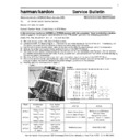
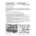
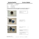
Location of IC upgrade for the AVR500/AVR7000:
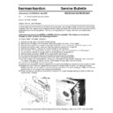
9) Replace DSP PC Board back into its (3) receptacle plugs atop the MAIN PCB.
10) Replace all screws, braces, and any cable ties that were cut during disassembly. Before tightening the
10) Replace all screws, braces, and any cable ties that were cut during disassembly. Before tightening the
screws, make sure all PCB’s and their RCA jacks are firmly seated in their respective holes in the rear
backplate. If using a power tool, use care and minimum effort to avoid damaging the various plastic
receptacles.
backplate. If using a power tool, use care and minimum effort to avoid damaging the various plastic
receptacles.
11) Plug both the 22 conductor ribbon cable and the 5 conductor molex cable back into their receptacles.
12) Replace the top cover and optical plugs.
13) Test unit by powering up the receiver and playing a music source in the Logic 7 mode.
AVR7000 ONLY: MODIFICATION OF THE DSP BOARD (replace IC101 AT27LV020A)
12) Replace the top cover and optical plugs.
13) Test unit by powering up the receiver and playing a music source in the Logic 7 mode.
AVR7000 ONLY: MODIFICATION OF THE DSP BOARD (replace IC101 AT27LV020A)
WARNING: FOLLOW PROPER STATIC CONTROL PROCEDURES and use caution during the installation of
new IC101 to prevent damage.
1) Remove the top cover, (16) Black Phillips screws at the sides and rear of the unit.
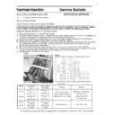
2) Locate the DSP PC Board and IC101 with the illustrations above.
3) Unsolder IC101 AT27LV020A and replace with hk part# J2131328001X. See illustration above for location
on PCB.
4) Replace top cover and all Phillips screws.
5) Test unit by powering up the receiver and playing a music source in the Logic 7 mode.
5) Test unit by powering up the receiver and playing a music source in the Logic 7 mode.
Model Serial
Number
120V
Serial Number
230V RDS
STATUS
ACTION
AVR7000
TH0003-01000
To
TH0003-05222
Modified by factory
Noise in Logic 7 Mode
Replace IC101
AT27LV020A
AVR7000
TH0003-05223
Or higher
Modified by factory
Modified by factory
NONE REQUIRED
Display

