Read Sony KV-HS29N90 Service Manual online
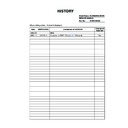
Date
SUPP./CORR.
Description of SUP/COR
Change of
main text
2002.12
NEW
-
2007. 1
CORR.-1
Correction of PART NO. (
Sec 6, 7
D board)
Yes
Model Name :KV-HS29/34/38N90
SERVICE MANUAL
Part No. : 9-965-354-02
HISTORY
When clicking an item, it’s detail is displayed.
SERVICE MANUAL
CHASSIS
AG-3F
MODEL
COMMANDER
DEST. CHASSIS NO.
MODEL
COMMANDER
DEST. CHASSIS NO.
KV-HS29N90
RM-999
WB
SCC-M05C-A
KV-HS34N90
RM-999
WB
SCC-M05B-A
KV-HS38N90
RM-999
WB
SCC-M05A-A
TRINITRON
®
COLOR TV
TV
VIDEO
DRC-MF
HD/DVD
1
2
3
4
5
6
7
8
0
9
JUMP
PROG
OPTION
RESET
A/B
V CENTER
PROG
INDEX
MENU
RM-999
KV-HS29N90,
KV-HS34N90,
KV-HS38N90
,
– 2 –
KV-HS29/34/38N90
RM-9997
SPECIFICATIONS
SAFETY-RELATED COMPONENT WARNING!!
COMPONENTS IDENTIFIED BY SHADING AND MARK
!
ON
THE SCHEMATIC DIAGRAMS, EXPLODED VIEWS AND IN THE
PARTS LIST ARE CRITICAL TO SAFE OPERATION. REPLACE
THESE COMPONENTS WITH SONY PARTS WHOSE PART
NUMBERS APPEAR AS SHOWN IN THIS MANUAL OR IN
SUPPLEMENTS PUBLISHED BY SONY.
PARTS LIST ARE CRITICAL TO SAFE OPERATION. REPLACE
THESE COMPONENTS WITH SONY PARTS WHOSE PART
NUMBERS APPEAR AS SHOWN IN THIS MANUAL OR IN
SUPPLEMENTS PUBLISHED BY SONY.
CAUTION
SHORT CIRCUIT THE ANODE OF THE PICTURE TUBE AND
THE ANODE CAP TO THE METAL CHASSIS, CRT SHIELD, OR
CARBON PAINTED ON THE CRT, AFTER REMOVING THE
ANODE.
THE ANODE CAP TO THE METAL CHASSIS, CRT SHIELD, OR
CARBON PAINTED ON THE CRT, AFTER REMOVING THE
ANODE.
– 3 –
KV-HS29/34/38N90
RM-9997
TABLE OF CONTENTS
Section
Title
Page
SELF DIAGNOSIS FUNCTION .................................. 4
1. DISASSEMBLY
1-1.
Rear Cover Removal .............................................. 8
1-2.
Speaker Box Removal ............................................ 8
1-3.
Chassis Assy Removal ............................................. 8
1-4.
Service Position ....................................................... 9
1-5.
DC Board Removal .................................................. 9
1-6.
J Board Removal ...................................................... 9
1-7.
D Board Removal .................................................. 10
1-8.
A, A1, and E Boards and B4 Block Removal ...... 10
1-9.
H1, H2, MS2, and F2 Boards Removal ................ 11
1-10. Picture Tube Removal (1) ...................................... 11
1-11.
1-11.
Picture Tube Removal (2) ...................................... 12
1-12. Harness Ranning .................................................... 13
2. SET-UP ADJUSTMENTS
2-1.
Beam Landing Adjustment .................................... 15
2-2.
Convergence Adjustment ....................................... 16
2-3.
Focus Adjustment .................................................. 18
2-4.
Neck Assy Twist Adjustment ................................. 18
2-5.
G2 (Screen) and White Blance Adjustments ......... 19
3. CIRCUIT ADJUSTMENTS
3-1.
Adjustments with Commander .............................. 20
3-2.
Adjustment Method ............................................... 21
3-3.
Picture Quality Adjustments .................................. 35
3-3-1. Preparation ......................................................... 35
3-3-2. NTSC Video Input ............................................. 36
3-3-3. NTSC RF Input ................................................. 36
3-3-4. PAL Video Input ................................................ 37
3-3-5. PAL RF Input ..................................................... 37
3-3-2. NTSC Video Input ............................................. 36
3-3-3. NTSC RF Input ................................................. 36
3-3-4. PAL Video Input ................................................ 37
3-3-5. PAL RF Input ..................................................... 37
Section
Title
Page
4. SAFETY RELATED ADJUSTMENTS
4-1.
HV Regulation Adjustment .................................... 38
4-2.
HV Hold-down Adjustment ................................... 38
4-2-1.
HV Protector Adjustments ................................ 38
4-2-2.
HV Protector Check ......................................... 38
4-3.
+B Max Voltage Confirmation ............................... 39
4-4.
+B OVP Confirmation ........................................... 39
5. DIAGRAMS
5-1.
Block Diagrams ...................................................... 40
5-2.
Circuit Boards Location ......................................... 58
5-3.
Schematic Diagrams ............................................... 59
5-4.
Semiconductors .................................................... 126
6. EXPLODED VIEWS
6-1.
Picture Tube .......................................................... 130
6-2.
Chassis .................................................................. 132
6-3.
Packing Materials ................................................. 134
7. ELECTRICAL PARTS LIST
................................... 135

