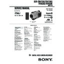
DCR-TRV130, DCR-TRV130E, DCR-TRV230, DCR-TRV230E, DCR-TRV235E, DCR-TRV325E, DCR-TRV330, DCR-TRV330E, DCR-TRV430E, DCR-TRV530, DCR-TRV530E, DCR-TRV725E, DCR-TRV730, DCR-TRV730E, DCR-TRV828, DCR-TRV828E, DCR-TRV830, DCR-TRV830E - Sony Movie Service Manual (repair manual)

dcr-trv130, dcr-trv130e, dcr-trv230, dcr-trv230e, dcr-trv235e, dcr-trv325e, dcr-trv330, dcr-trv330e, dcr-trv430e, dcr-trv530, dcr-trv530e, dcr-trv725e, dcr-trv730, dcr-trv730e, dcr-trv828, dcr-trv828e, dcr-trv830, dcr-trv830e service manual
Model
DCR-TRV130 DCR-TRV130E DCR-TRV230 DCR-TRV230E DCR-TRV235E DCR-TRV325E DCR-TRV330 DCR-TRV330E DCR-TRV430E DCR-TRV530 DCR-TRV530E DCR-TRV725E DCR-TRV730 DCR-TRV730E DCR-TRV828 DCR-TRV828E DCR-TRV830 DCR-TRV830E
Pages
49
Size
1.68 MB
Type
PDF
Document
Service Manual
Brand
Device
Movie / 8mm Video MECHANICAL ADJUSTMENT MANUAL IX
File
dcr-trv130-dcr-trv130e-dcr-trv230-dcr-trv230e-dcr-.pdf
Date

Read Sony DCR-TRV130 / DCR-TRV130E / DCR-TRV230 / DCR-TRV230E / DCR-TRV235E / DCR-TRV325E / DCR-TRV330 / DCR-TRV330E / DCR-TRV430E / DCR-TRV530 / DCR-TRV530E / DCR-TRV725E / DCR-TRV730 / DCR-TRV730E / DCR-TRV828 / DCR-TRV828E / DCR-TRV830 / DCR-TRV830E Service Manual online

8mm Video MECHANICAL ADJUSTMENT MANUAL IX
MECHANISM DECK
Please use this manual with the service manual of the respective models.
Ver. 1.3  2007. 02
M2000 MECHANISM
Revised-1
The M2000 mechanism is comprised of the two different types
of mechanism. Before starting repairing, be sure to identify the
type of mechanism. (See page 3 and 4 “2. Method to Identify
the Type”)
— 2 —
TABLE OF CONTENTS
1.
Preparations for Check, Adjustment and
Replacement of Mechanism Block
1-1.
Before Replacement, Check or Adjustment ······················· 3
1-2.
Method to Identify the Type ··············································· 3
1-3.
Service Jigs and Tools ························································ 5
1-4.
Mode Selector II Operating Procedure ······························· 6
2.
Periodic Inspection and Maintenance
2-1.
Rotary Drum Cleaning ····················································· 10
2-2.
Tape Path System Cleaning ·············································· 10
2-3.
Periodic Inspection List ···················································· 11
2-4.
Applying Oil and Grease ·················································· 11
3.
Before Replacement, Check or Adjustment
3-1.
Phase Adjustment ····························································· 12
3-2.
Cassette compartment assembly ······································· 13
4.
Check, Adjustment and Replacement
4-1.
Drum Assembly ································································ 14
4-2.
HCL Arm Assembly, Loading Motor Assembly ·············· 15
4-3.
Drum Base Assembly, Drum Earth ·································· 16
4-4.
Guide Rail T2, Capstan Motor ········································· 17
4-5.
Blind Plate, Lock Guide ··················································· 18
4-6.
Reel Table (T) Assembly, T Soft Assembly ····················· 19
4-7.
S Ratchet RE Plate, Cassette Guide S ······························ 20
4-8.
R Drive Gear Assembly, LS Cam Plate (LS type A) ········ 21
4-9.
LS Cam Plate Position Adjustment (LS type A only) ······ 22
4-10. R Drive Gear Assembly (LS type B) ································ 23
4-11. LS Chassis Block Assembly ············································· 24
4-12. TG7 Arm Block Assembly, Pinch Arm Assembly ··········· 25
4-13. Guide Base (T) Block Assembly, Guide Base (S) Block
Assembly ·········································································· 26
4-14. TG1 Arm, Reel Table (S) Assembly, Push Switch (3Key) ·· 27
4-15. Hall Element (H001, H002 (T/S Reel)),
Photo Transistor (Q001, Q002 (TAPE TOP/TAPE END)),
LED (D001 (TAPE LED)) ················································ 28
4-16. LS Guide Roller, Guide Lock Plate (T), Pinch Pusher
Assembly, Eject Arm ························································ 29
4-17. Rotary Switch, Cam Relay Gear, Change Gear Assembly,
Timing Belt ······································································· 30
4-18. Guide Gear (S) Assembly, Guide Gear (T) Assembly,
Cam Relay Gear 1, Guide Lock Plate (S) ························ 31
4-19. LD Gear 4, Cam Gear 1, HC Drive Arm ·························· 32
4-20. M Slide Plate Assembly, LS Arm Assembly, Cam Gear 2,
GL Arm Assembly ···························································· 33
5.
Adjustment
5-1.
Check and Adjustment of TG1 Back-tension Position ····· 34
5-2.
Check and Adjustment of FWD/RVS Back-tension ········· 35
5-3.
Capstan Motor Azimuth Position Adjustment ·················· 36
5-4.
Tape Path Adjustment ······················································· 37
6.
Exploded Views
6-1.
Cassette Compartment Assy, Drum Assy ························· 41
6-2.
LS Chassis Block Assembly ············································· 42
6-3.
Mechanical Chassis Block Assembly-1 ··························· 43
6-4.
Mechanical Chassis Block Assembly-2 ··························· 44
7.
Printed Wiring Boards and
Schematic Diagrams
.............................................. 45
— 3 —
1. Preparations for Check, Adjustment and Replacement of Mechanism Block
1-1. Before Replacement, Check or Adjustment
• Refer to the “DISASSEMBLY” section of the SERVICE MANUAL of the respective models for details of removing cabinets and printed
wiring boards.
• When checking a mechanism or making any adjustment to the mechanism or replacing mechanical parts, be sure to use the Mode Selector
II and select the appropriate status of the mechanical deck such that the mechanical status is suitable for the desired work. Refer to section
“1-4. Mode Selector II Operating Procedure” for details on how to enter the mode shown in a rectangle [       ] mode in the sequent sections
of this manual.
* Assemble and adjust the parts in the [USE] mode if any mode is not specified in this manual.
1-2. Method to Identify the Type
1)
In the M2000 mechanism, the LS chassis assembly is installed in the two different methods: They are type-A and type-B.
LS Type A: The LS cam plate is used.
LS Type B: The LS cam plate is not used. Thin groove of the LS cam plate is embedded in the LS chassis.
4mm
2mm
LS type A
LS type B
S reel
Two screws 
(M1.7)
HLC cut (1.8 
×
 4 
×
 0.5)
The HLC cut (1.8 
×
 4 
×
 0.5) is not 
necessary for reassembling.
LS cam plate
S reel
Two screws 
(M1.7)
LS cam plate
[Without LS cam plate] 
[Without HLC cut] 
[With HLC cut] 
LS chassis assembly 
LS chassis assembly 
S reel
S reel
LS cam plate
LS chassis assembly 
groove
LS chassis assembly 
groove
— 4 —
2)
There are two types of the mechanism chassis assembly.
Mechanism chassis assembly type A: Shaft A is secured by a screw.
Mechanism chassis assembly type B: Shaft B is secured by a stop ring 1.2 (E type).
S reel
Shaft A
Screw (M1.4)
LS guide roller A
Stop ring 1.2 (E type)
Shaft A:
Secured by a screw 
Shaft A: Secured by 
a stop ring (E type)
LS arm assembly
LS chassis assembly
LS chassis assembly
Mechanism chassis type A
Mechanism chassis type B
Shaft A
LS chassis assembly
S reel
Page of 49
Display

Download Sony DCR-TRV130 / DCR-TRV130E / DCR-TRV230 / DCR-TRV230E / DCR-TRV235E / DCR-TRV325E / DCR-TRV330 / DCR-TRV330E / DCR-TRV430E / DCR-TRV530 / DCR-TRV530E / DCR-TRV725E / DCR-TRV730 / DCR-TRV730E / DCR-TRV828 / DCR-TRV828E / DCR-TRV830 / DCR-TRV830E Service Manual (Repair Manual)

Here you can read online and download Sony DCR-TRV130 / DCR-TRV130E / DCR-TRV230 / DCR-TRV230E / DCR-TRV235E / DCR-TRV325E / DCR-TRV330 / DCR-TRV330E / DCR-TRV430E / DCR-TRV530 / DCR-TRV530E / DCR-TRV725E / DCR-TRV730 / DCR-TRV730E / DCR-TRV828 / DCR-TRV828E / DCR-TRV830 / DCR-TRV830E Service Manual in PDF. DCR-TRV130 / DCR-TRV130E / DCR-TRV230 / DCR-TRV230E / DCR-TRV235E / DCR-TRV325E / DCR-TRV330 / DCR-TRV330E / DCR-TRV430E / DCR-TRV530 / DCR-TRV530E / DCR-TRV725E / DCR-TRV730 / DCR-TRV730E / DCR-TRV828 / DCR-TRV828E / DCR-TRV830 / DCR-TRV830E service manual will guide through the process and help you recover, restore, fix, disassemble and repair Sony DCR-TRV130 / DCR-TRV130E / DCR-TRV230 / DCR-TRV230E / DCR-TRV235E / DCR-TRV325E / DCR-TRV330 / DCR-TRV330E / DCR-TRV430E / DCR-TRV530 / DCR-TRV530E / DCR-TRV725E / DCR-TRV730 / DCR-TRV730E / DCR-TRV828 / DCR-TRV828E / DCR-TRV830 / DCR-TRV830E Movie. Information contained in service manuals typically includes schematics / circuit diagrams, wiring diagrams, block diagrams, printed wiring boards, exploded views, parts list, disassembly / assembly, pcb.