Read Sony DCR-TR8000E / DCR-TR8100E / DCR-TRV120 / DCR-TRV120E / DCR-TRV120P / DCR-TRV125E (serv.man2) Service Manual online
SERVICE MANUAL
2001.01
RMT-814
SUPPLEMENT-1
File this supplement with the service manual.
(PV00-020)
• Addition of SERVICE NOTE. (Change of IC type.)
• Correction of FRAME SCHEMATIC DIAGRAMS.
• Suffix No. of the board is changed.
• Correction of FRAME SCHEMATIC DIAGRAMS.
• Suffix No. of the board is changed.
(
CF-69 board has been changed from –11 (21) to –12 (22) .
)
VC-235 board has been changed from –12 (22, 23) to –13 (23, 33) .
• Correction and change of SCHEMATIC DIAGRAMS.
• Correction and change of ADJUSTMENTS.
• Change of REPAIR PARTS LIST.
• Correction and change of ADJUSTMENTS.
• Change of REPAIR PARTS LIST.
DCR-TRV120/TRV120E/TRV120P/TRV125E/
TR8000E/TR8100E
US Model
Canadian Model
DCR-TRV120
AEP Model
DCR-TRV120E/TRV125E/TR8000E/TR8100E
UK Model
East European Model
North European Model
Russian Model
DCR-TRV120E/TR8000E
E Model
DCR-TRV120/TRV120E/TRV120P
Hong Kong Model
DCR-TRV120/TRV120E
Korea Model
DCR-TRV120P
Argentina Model
DCR-TRV120P
Brazilian Model
DCR-TRV120
Australian Model
Chinese Model
DCR-TRV120E
Tourist Model
DCR-TRV120/TRV120E
– 2 –
DCR-TRV120/TRV120E/TRV120P/TRV125E/
TR8000E/TR8100E
TR8000E/TR8100E
SERVICE NOTE
4.
Change of IC (Service Manual Page 8)
4-1.
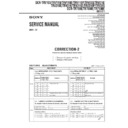
Change of IC2201 type on the VC-235 board.
The type of IC2201 was changed from existing HG75C012FFL to
HG75C0SFL, or to MB87M1011PFF-G-BND. In each type, the
EEPROM data and mounted parts were changed.
Also, which type of IC is mounted can be checked with the adjust-
ing remote commander.
HG75C0SFL, or to MB87M1011PFF-G-BND. In each type, the
EEPROM data and mounted parts were changed.
Also, which type of IC is mounted can be checked with the adjust-
ing remote commander.
Type check method:
1) Select page: 6, address: 6F, and set data: 01.
2) Select page: 6, and address: FF.
3) The type of IC2201 can be checked from the displayed data.
1) Select page: 6, address: 6F, and set data: 01.
2) Select page: 6, and address: FF.
3) The type of IC2201 can be checked from the displayed data.
Data change method:
1) Select page: 0, address: 01, and set data: 01.
2) Select page: F, and input the data in the following table.
1) Select page: 0, address: 01, and set data: 01.
2) Select page: F, and input the data in the following table.
Note:
To write in the non-volatile memory (EEPROM), press
the PAUSE button of the adjustment remote commander
each time to se the data.
the PAUSE button of the adjustment remote commander
each time to se the data.
3) Select page: 0, address: 01, and set data: 00.
Type
Data
MB87M1011PFF-G-BND
00
HG75C012SFL
03
HG75C012FFL,
MB87M1101PFF-G-BND
HG75C012SFL
Address
DATA
Address
DATA
NTSC
PAL
NTSC
PAL
23
14
15
23
1C
1D
67
69
65
67
A0
A0
68
64
72
68
AA
A8
Note:
No data is changed resulting from the change from
HG75C012 FFL to HG75C012SFL.
HG75C012 FFL to HG75C012SFL.
• Differences of mounted parts
IC TYPE HG75C012SFL MB87M1101PFF MB87M1101PFF
Ref.No.
1
2
-G-BND
3
C2214
0.1u
0.1u
C2222
0.1u
0.1u
C2224
0.1u
0.1u
C2236
0.1u
0.1u
C3349
1u
C3350
1u
C3351
0.1u
IC2201
HG75C012FFL
HG75C012SFL
MB87M1101PFF
-G-BND
IC3304
TK11215BMCL
R1303
56K
330K
330K
R2223
8.2K
8.2K
R3306
0
0
• Change of IC2201 type from 1, 2 to 3:
No abnormality will arise in operation, even if C2214, C2222,
C2224, C2236 and R2223 are mounted.
C2224, C2236 and R2223 are mounted.
• Change of IC2201 type from 1 to 2:
Mount on C2214, C2222, C2224, C2236 and R2223.
4-2.
Change of IC4501 on the VC-235 board.
Due to a change of IC4501 (mechanism control), the version is
updated such as MP1
updated such as MP1
→
MP2
→
MP3
→
MP4. In each version,
the EEPROM data was changed.
Also, the version of IC4501 can be checked with the adjusting
remote commander.
Also, the version of IC4501 can be checked with the adjusting
remote commander.
Note 1:
Changing the version does not make any changes in sche-
matic diagrams and the rest.
matic diagrams and the rest.
Note 2:
Make it sure to confirm the version after replacing IC
4501.
4501.
Version check method:
1) Select page: 3, and address: FF.
2) The version of IC4501 can be checked from the displayed data.
1) Select page: 3, and address: FF.
2) The version of IC4501 can be checked from the displayed data.
Data change method:
1) Select page: 0, address: 01, and set data: 01.
2) Select page: 8, and input the data in the following table.
1) Select page: 0, address: 01, and set data: 01.
2) Select page: 8, and input the data in the following table.
Note:
To write in the non-volatile memory (EEPROM), press
the PAUSE button of the adjustment remote commander
each time to set the data.
the PAUSE button of the adjustment remote commander
each time to set the data.
3) Select page: 0, address: 01, and set data: 00.
4-3.
Change of IC4902 on the VC-235 board.
IC4902 (VC control) has been changed to MB91192PFF-G-117-
BND-ER.
Because of this change, the EEPROM data is changed.
BND-ER.
Because of this change, the EEPROM data is changed.
Data change method:
1) Select page: 0, address: 01, and set data: 01.
2) Select page: 6, address: FF, and set data: 06.
3) Select page: F, address: 1F, set data: C2 (NTSC) or data: E0
1) Select page: 0, address: 01, and set data: 01.
2) Select page: 6, address: FF, and set data: 06.
3) Select page: F, address: 1F, set data: C2 (NTSC) or data: E0
(PAL), and press the PAUSE button of the adjustment remote
commander.
commander.
4) Select page: 0, address: 01, and set data: 00.
Data
Version
12
MP1
14
MP2
15
MP3
16
MP4
Version
MP1
MP2
MP3
MP4
Address
A5
00
01
01
01
A7
31
31
70
70
A8
05
05
28
28
DCR-TRV120/TRV120E/TRV120P/TRV125E/
TR8000E/TR8100E
– 3 –
– 4 –
SECTION 4
PRINTED WIRING BOARDS AND SCHEMATIC DIAGRAMS
&
: Points added portion.
-
: Points changed portion.
!
: Points deleted portion.
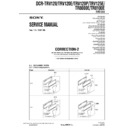
4-1. FRAME SCHEMATIC DIAGRAMS
FRAME (1/2) SCHEMATIC DIAGRAM
(Service manual page 4-3, Location J-5 to O-16)
• Correction
(Service manual page 4-3, Location J-5 to O-16)
• Correction
8
7
6
5
4
3
2
1
1
2
3
4
5
6
7
8
9
10
CN4402
10P
1
2
3
4
5
6
7
8
9
10
12
11
10
9
8
7
6
5
4
3
2
1
CN4403
12P
1
2
3
4
5
6
7
8
9
10
11
12
15
14
13
12
11
10
9
8
7
6
5
4
3
2
1
CN4404
15P
1
2
3
4
5
6
7
8
9
10
11
12
13
14
15
1
2
3
4
5
6
7
8
9
10
11
12
13
14
15
16
CN4401
8P
1
2
3
4
5
6
7
8
10P
CN1101
1
2
3
4
5
6
7
8
9
10
15
16
17
18
19
20
21
22
23
24
25
26
27
28
29
30
31
32
16P
CN3101
1
LP2Y
2
LP2X
3
GND
4
LP1X
5
LP1Y
6
GND
7
GND
8
GND
9
XODD
10
YODD
11
GND
12
XEVEN
13
YEVEN
14
GND
15
FEY
16
FEX
M
PG
FG
COM
W
W
V
V
U
U
YODD
PG
FG-PG_COM
FG
XODD
GND
LP1Y
LP1X
GND
FP-220
LP2X
FP
LP2Y
FP
GND
FP-38 FLEXIBLE
GND
FP-221 FLEXIBLE
GND
FEX
XEVEN
YEVEN
FEY
GND
COM
W
W
V
V
U
U
LM(+)
LM(+)
LM(-)
LM(-)
M-SW(C)
M-SW(B)
M-SW(A)
COM_GND
LM(-)
M-SW(A)
LM(+)
COM_GND
M-SW(C)
LM(-)
M-SW(B)
LM(+)
FG-PG_COM
MT_GND
FRC
REG_GND
VCC_2
ST
AND_BY
VS
MT_GND
FG_OUT
DEW
VCC_1
OFFSET_ADJ
VS
MT_GND
FRC
REG_GND
VCC_2
ST
AND_BY
VS
MT_GND
FG_OUT
DEW
VCC_1
OFFSET_ADJ
VS
C_LOCK_SW
T
APE_LED(K)
S_REEL(+)
HI8_MP
REG_GND
SENSOR_VCC
T
APE_END(C)
ME/MP
T_REEL(+)
REC_PROOF
S_REEL(-)
T_REEL(-)
T
APE_TOP(C)
HALL_COM
T
APE_LED(A)
C_LOCK_SW
T
APE_LED(K)
S_REEL(+)
HI8_MP
REG_GND
SENSOR_VCC
T
APE_END(C)
ME/MP
T_REEL(+)
REC_PROOF
S_REEL(-)
T_REEL(-)
T
APE_TOP(C)
HALL_COM
T
APE_LED(A)
SHOE_UNREG
SHOE_UNREG_GND
SHOE_UNREG_GND
SHOE_UNREG
LANC_SIG/LIGHT_PWM
SHOE_ID1
SHOE_MIC_GND
SHOE_MIC_L
SHOE_UNREG_GND
SHOE_ID2
HOTSHOE_ID1
A_4.75V
MF_A
MIC_R
ZOOM_MIC_CONT
MF_B
AU_2.8V
SHOE_MIC_L
MIC_L
HP_R_OUT
REG_GND
REG_GND
MF_LED
XMIC_MONO
EXT_MIC_DET
HP_JACK_IN
SIRCS_SIG
HP_L_OUT
M903
LOADING
MOTOR
S901
MODE
SWITCH
VIDEO
HEAD
EVEN
M
FG
PG
PG
FG
M
M901
DRUM MOTOR
M902
CAPSTAN MOTOR
FP-249 FLEXIBLE
FP-355
FLEXIBLE
FLEXIBLE
FP-356
FLEXIBLE
FLEXIBLE
FLEXIBLE
ODD
FLYING
ERASE
ERASE
B700 MECHANISM
DEW
SENSOR
SENSOR
4-2. PRINTED WIRING BOARDS AND SCHEMATIC DIAGRAMS
CF-69 (USER CONTROL) SCHEMATIC DIAGRAM
(Service manual page 4-64, Location B-11 to F-17)
• Suffix No. of the board is changed (
(Service manual page 4-64, Location B-11 to F-17)
• Suffix No. of the board is changed (
–11 (21)
t
–12 (22)
).
Former Type (Suffix -11)
New Type (Suffix -12)
7.3
4.1
6.7
2.3
3
0
R047
XX
C007
XX
L002
XX
R029
XX
R033
XX
R037
390
R019
XX
R034
2SA1362-YG-EL
Q003
XX
R035
XX
Q005
XX
Q004
XX
C006
XX
Q006
XX
R036
S010
2SC4116YG-TE85L
Q002
XX
L003
XX
C005
3900
R024
XX
R018
XX
C008
33
R013
XX
R028
XX
L001
XX
R046
S014
S007
XX
C004
XX
IC001
1
2
3
4
5
1500
R015
2200
R020
TA.B
Z macro
TA.B
Q002,003
BACK LIGHT SWITCH
BACK LIGHT SWITCH
PB ZOOM
TITLE
MENU
CT
7.3
4.1
6.7
2.3
3
XX
C007
XX
L002
XX
R029
XX
R033
XX
R037
390
R019
XX
R034
2SA1362-YG-EL
Q003
XX
R035
XX
Q005
XX
Q004
XX
C006
XX
Q006
XX
R036
S010
2SC4116YG-TE85L
Q002
XX
L003
XX
C005
3900
R024
XX
R018
33
R013
XX
R028
XX
L001
S014
S007
XX
C004
1500
R015
2200
R020
T
A.B
Z macro
TA.B
Q002,003
BACK LIGHT SWITCH
BACK LIGHT SWITCH
PB ZOOM
TITLE
MENU
CT
1u
C011
1u
C009
1u
C010
@
]
]
\
(
*
)
DCR-TRV120/TRV120E/TRV120P/TRV125E/
TR8000E/TR8100E
TR8000E/TR8100E
– 5 –
– 6 –
• For Printed Wiring Board.
• There are a few cases that the part isn't mounted in this model
• There are a few cases that the part isn't mounted in this model
is printed on this diagram.
• Chip transistor
E
B
C
CF-69 (USER CONTROL) PRINTED WIRING BOARD
– Ref. No.: CF-69 board; 20,000 series –
– DCR-TRV120/TRV120E/TRV120P/TRV125E –
(Service manual page 4-67 to 70)
(Service manual page 4-67 to 70)
PLAY
–
+
INDEX
DELETE
MEMORY
MIX
FADER
BACK
LIGHT
PROGRAM
AE
EXPOSURE
MENU
TITLE
PB ZOOM
PICTURE
EFFECT
SEL/
PUSH EXEC
END SEARCH
DISPLAY
DATA CODE
DIGITAL EFFECT
MEMORY
USER CONTROL
CF-69


