Read Sony DCR-DVD105 (serv.man2) Service Manual online
MANUAL DE SERVIÇO
Sony EMCS Co.
LEVEL
2
NOTA DE SERVIÇO
ESPECIFICAÇÕES
DIAGRAMAS EM BLOCOS
DIAGRAMAS ESQUEMÁTICOS
DESMONTAGEM
LISTA DE PEÇAS PARA REPARO
PLACAS DE CIRCUITO IMPRESSO
Link
Revision History
Instruções do
Acrobat Reader
Ver 1.0 2005.12
DIGITAL VIDEO CAMERA RECORDER
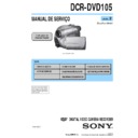
Foto: DCR-DVD105
Os componentes identificados
com a marca 0 são criticos
para a segurança. Somente os
substitua por peças especificadas
nesse manual.
com a marca 0 são criticos
para a segurança. Somente os
substitua por peças especificadas
nesse manual.
© 2006.02
Publicado por Sony Brasil Ltda.- Engenharia de Qualidade
Brazilian Model
DCR-DVD105
9-890-022-31
144
Sistema
Formato de compressão de vídeo
MPEG2/JPEG (Imagens estáticas)
Formato de compressão de áudio
DCR-DVD105
Dolby Digital 2ch
Dolby Digital Stereo Creator
DCR-DVD305
Dolby Digital 2/5.1ch
Dolby Digital 5.1 Creator
Dolby Digital 2ch
Dolby Digital Stereo Creator
DCR-DVD305
Dolby Digital 2/5.1ch
Dolby Digital 5.1 Creator
Sinal de vídeo
Sistema de cor NTSC, padrão EIA
Discos utilizáveis
DVD-R/DVD-RW/DVD+RW de 8cm
Formato de gravação
Filmes
DVD-R:
DVD-R:
DVD-VIDEO
DVD-RW: DVD-VIDEO (modo VIDEO),
DVD-Video Recording
(modo VR)
(modo VR)
DVD+RW: DVD+RW Video
Imagens estáticas
Exif
Exif
*1
Ver.2.2
Tempo de gravação/reprodução
HQ: Aprox. 20 min
SP: Aprox. 30 min
LP: Aprox. 60 min
SP: Aprox. 30 min
LP: Aprox. 60 min
Visor eletrônico
Visor eletrônico
colorido
colorido
Dispositivo de imagem
DCR-DVD105
CCD (Charge Coupled Device - Dispositivo de
Transferência de Carga) de 3 mm (tipo 1/6)
Bruto:
Aprox. 680 000 pixels
Efetivo (Filme):
Aprox. 340 000 pixels
Efetivo (Foto):
Aprox. 340 000 pixels
DCR-DVD305
CCD (Charge Coupled Device - Dispositivo de
Transferência de Carga) de 3,27mm (tipo 1/5.5)
Bruto:
Aprox. 1 070 000 pixels
Efetivo (Filme,4:3)
Aprox. 690 000 pixels
Efetivo (Filme,16:9)
Aprox. 670 000 pixels
Efetivo (Foto, 4:3)
Aprox. 1 000 000 pixels
Efetivo (Foto, 16:9)
Aprox. 750 000 pixels
CCD (Charge Coupled Device - Dispositivo de
Transferência de Carga) de 3 mm (tipo 1/6)
Bruto:
Aprox. 680 000 pixels
Efetivo (Filme):
Aprox. 340 000 pixels
Efetivo (Foto):
Aprox. 340 000 pixels
DCR-DVD305
CCD (Charge Coupled Device - Dispositivo de
Transferência de Carga) de 3,27mm (tipo 1/5.5)
Bruto:
Aprox. 1 070 000 pixels
Efetivo (Filme,4:3)
Aprox. 690 000 pixels
Efetivo (Filme,16:9)
Aprox. 670 000 pixels
Efetivo (Foto, 4:3)
Aprox. 1 000 000 pixels
Efetivo (Foto, 16:9)
Aprox. 750 000 pixels
Lente
Lente Carl Zeiss Vario-Tessar
Diâmetro do filtro: 25mm
DCR-DVD105
Óptico:20×, Digital:40×, 800×
F=1,8-3,1
DCR-DVD305
Óptico:12×, Digital:24×, 800×
F=1,8-2,5
Diâmetro do filtro: 25mm
DCR-DVD105
Óptico:20×, Digital:40×, 800×
F=1,8-3,1
DCR-DVD305
Óptico:12×, Digital:24×, 800×
F=1,8-2,5
Distância focal
DCR-DVD105
f=2,3 - 46mm
Quando convertida para uma câmera
fotográfica de 35 mm
Para imagens com movimento:
44 - 880mm
Para imagens estáticas:
44 - 880mm
DCR-DVD305
f=3,0 - 36mm
Quando convertida para uma câmera
fotográfica de 35 mm
Para imagens com movimento:
46 - 628,5mm (modo 16:9)
f=2,3 - 46mm
Quando convertida para uma câmera
fotográfica de 35 mm
Para imagens com movimento:
44 - 880mm
Para imagens estáticas:
44 - 880mm
DCR-DVD305
f=3,0 - 36mm
Quando convertida para uma câmera
fotográfica de 35 mm
Para imagens com movimento:
46 - 628,5mm (modo 16:9)
*2
48 - 576mm (modo 4:3)
Para imagens estáticas:
40 - 480mm (modo 4:3)
43,6 - 523,2mm (modo 16:9)
Para imagens estáticas:
40 - 480mm (modo 4:3)
43,6 - 523,2mm (modo 16:9)
Temperatura de cor
[AUTO], [UM TOQUE], [INTERIOR] (3 200
K), [EXTERIOR] (5 800 K)
K), [EXTERIOR] (5 800 K)
Iluminação mínima
DCR-DVD105
5 lx (lux) (F1,8)
0 lx (lux) (na função NightShot plus)
5 lx (lux) (F1,8)
0 lx (lux) (na função NightShot plus)
*3
DCR-DVD305
7 lx (lux) (F1,8)
0 lx (lux) (na função NightShot plus)
7 lx (lux) (F1,8)
0 lx (lux) (na função NightShot plus)
*3
*1
“Exif” é o formato de arquivo para imagens
estáticas, estabelecido pela JEITA (Japan
Electronics and Information Technology
Industries Association). Os arquivos neste
formato podem conter informação adicional,
como a informação de ajuste da câmera no
momento da gravação.
estáticas, estabelecido pela JEITA (Japan
Electronics and Information Technology
Industries Association). Os arquivos neste
formato podem conter informação adicional,
como a informação de ajuste da câmera no
momento da gravação.
*2
No modo 16:9, os números da distância focal
são números reais resultantes dos pixels de
grande-angular.
são números reais resultantes dos pixels de
grande-angular.
*3
Objetos que não podem ser vistos no escuro
podem ser filmados com raios infravermelhos.
podem ser filmados com raios infravermelhos.
• Fabricado sob licença dos Laboratórios Dolby.
Especificações técnicas
145
In
fo
rm
a
çõ
e
s A
d
ic
io
n
a
is
Conectores de entrada/saída
DCR-DVD105
DCR-DVD105
Saída de áudio/vídeo
Conector de 10 pinos
sinal de vídeo: 1 Vp-p, 75
sinal de vídeo: 1 Vp-p, 75
Ω (ohms), não
balanceado
Luminância: 1 Vp-p, 75
Luminância: 1 Vp-p, 75
Ω (ohms), não
balanceado
Crominância: 0,286 Vp-p, 75
Crominância: 0,286 Vp-p, 75
Ω (ohms), não
balanceado
Sinal de áudio: 327 mV (com impedância de
carga de 47 k
Sinal de áudio: 327 mV (com impedância de
carga de 47 k
Ω (kilohms)), Impedância de saída
menor que 2,2 k
Ω (kilohms)
DCR-DVD305
Entrada/saída de áudio/vídeo
Conector de 10 pinos
Chave automática de entrada/saída
Sinal de vídeo: 1 Vp-p, 75
Chave automática de entrada/saída
Sinal de vídeo: 1 Vp-p, 75
Ω (ohms), não
balanceado
Luminância: 1 Vp-p, 75
Luminância: 1 Vp-p, 75
Ω (ohms), não
balanceado
Crominância: 0,286 Vp-p, 75
Crominância: 0,286 Vp-p, 75
Ω (ohms), não
balanceado
Sinal de áudio: 327 mV (com impedância de
carga de 47 k
Sinal de áudio: 327 mV (com impedância de
carga de 47 k
Ω (kilohms)), Impedância de
entrada maior que 47 k
Ω (kilohms), Impedância
de saída menor que 2,2 k
Ω (kilohms)
Tomada USB
mini-B
Tomada REMOTE
Minitomada estéreo (Ø2,5 mm)
Tela LCD
Imagem
DCR-DVD105
6,2 cm (tipo 2,5)
DCR-DVD305
6,9 cm (tipo 2,7, relação de aspecto 16:9)
6,2 cm (tipo 2,5)
DCR-DVD305
6,9 cm (tipo 2,7, relação de aspecto 16:9)
Número total de pontos
123 200 (560
× 220)
Geral
Alimentação
7,2 V (bateria)
8,4 V (Adaptador de alimentação CA)
8,4 V (Adaptador de alimentação CA)
Consumo médio
Durante a filmagem com a câmera usando
a tela LCD
DCR-DVD105: 2,7W
DCR-DVD305: 3,6W
Visor eletrônico
DCR-DVD105: 2,4W
DCR-DVD305: 3,1W
a tela LCD
DCR-DVD105: 2,7W
DCR-DVD305: 3,6W
Visor eletrônico
DCR-DVD105: 2,4W
DCR-DVD305: 3,1W
Temperatura de operação
0°C a + 40°C
Temperatura de armazenamento
-20°C a + 60°C
Dimensões (Aprox.)
54 × 88 × 129mm (L×A×P)
Peso (Aprox.)
DCR-DVD105
380 g somente a unidade principal
430 g incluindo a bateria recarregável
NP-FP50 e o disco
DCR-DVD305
400 g somente a unidade principal
460 g incluindo a bateria recarregável
NP-FP50 e o disco
380 g somente a unidade principal
430 g incluindo a bateria recarregável
NP-FP50 e o disco
DCR-DVD305
400 g somente a unidade principal
460 g incluindo a bateria recarregável
NP-FP50 e o disco
Acessórios fornecidos
Consulte a página 18.
Adaptador de alimentação CA
AC-L25A/L25B
AC-L25A/L25B
Alimentação
AC 100 - 240 V, 50/60 Hz
Consumo de corrente
0,35 - 0,18 A
Consumo
18W
Tensão de saída
DC 8,4V*
Temperatura de operação
0°C a + 40°C
Temperatura de armazenamento
-20°C a + 60°C
Dimensões (Aprox.)
56 × 31
× 100 mm (L× Α× P) excluindo partes
salientes
Peso (Aprox.)
190 g excluindo o cabo de alimentação
* Consulte outras especificações na etiqueta no
adaptador de alimentação CA.
— 4 —
DCR-DVD105
1.
Check the area of your repair for unsoldered or poorly-soldered
connections. Check the entire board surface for solder splashes
and bridges.
connections. Check the entire board surface for solder splashes
and bridges.
2.
Check the interboard wiring to ensure that no wires are
"pinched" or contact high-wattage resistors.
"pinched" or contact high-wattage resistors.
3.
Look for unauthorized replacement parts, particularly
transistors, that were installed during a previous repair. Point
them out to the customer and recommend their replacement.
transistors, that were installed during a previous repair. Point
them out to the customer and recommend their replacement.
4.
Look for parts which, through functioning, show obvious signs
of deterioration. Point them out to the customer and
recommend their replacement.
of deterioration. Point them out to the customer and
recommend their replacement.
5.
Check the B+ voltage to see it is at the values specified.
6.
Flexible Circuit Board Repairing
• Keep the temperature of the soldering iron around 270˚C
during repairing.
• Do not touch the soldering iron on the same conductor of the
circuit board (within 3 times).
• Be careful not to apply force on the conductor when soldering
or unsoldering.
VERIFICAÇÃO GERAL DE SEGURANÇA
After correcting the original service problem, perform the following
safety checks before releasing the set to the customer.
Unleaded solder
Boards requiring use of unleaded solder are printed with the lead-
free mark (LF) indicating the solder contains no lead.
(Caution: Some printed circuit boards may not come printed with
the lead free mark due to their particular size.)
free mark (LF) indicating the solder contains no lead.
(Caution: Some printed circuit boards may not come printed with
the lead free mark due to their particular size.)
: LEAD FREE MARK
Unleaded solder has the following characteristics.
• Unleaded solder melts at a temperature about 40
• Unleaded solder melts at a temperature about 40
°
C higher than
ordinary solder.
Ordinary soldering irons can be used but the iron tip has to be
applied to the solder joint for a slightly longer time.
Soldering irons using a temperature regulator should be set to
about 350
Ordinary soldering irons can be used but the iron tip has to be
applied to the solder joint for a slightly longer time.
Soldering irons using a temperature regulator should be set to
about 350
°
C.
Caution: The printed pattern (copper foil) may peel away if the
heated tip is applied for too long, so be careful!
heated tip is applied for too long, so be careful!
• Strong viscosity
Unleaded solder is more viscous (sticky, less prone to flow) than
ordinary solder so use caution not to let solder bridges occur such
as on IC pins, etc.
ordinary solder so use caution not to let solder bridges occur such
as on IC pins, etc.
• Usable with ordinary solder
It is best to use only unleaded solder but unleaded solder may
also be added to ordinary solder.
also be added to ordinary solder.
SAFETY-RELATED COMPONENT WARNING!!
COMPONENTS IDENTIFIED BY MARK
0
OR DOTTED LINE WITH
MARK
0
ON THE SCHEMATIC DIAGRAMS AND IN THE PARTS
LIST ARE CRITICAL TO SAFE OPERATION. REPLACE THESE
COMPONENTS WITH SONY PARTS WHOSE PART NUMBERS
APPEAR AS SHOWN IN THIS MANUAL OR IN SUPPLEMENTS
PUBLISHED BY SONY.
COMPONENTS WITH SONY PARTS WHOSE PART NUMBERS
APPEAR AS SHOWN IN THIS MANUAL OR IN SUPPLEMENTS
PUBLISHED BY SONY.
ATTENTION AU COMPOSANT AYANT RAPPORT
À LA SÉCURITÉ!
LES COMPOSANTS IDENTIFÉS PAR UNE MARQUE
0
SUR LES
DIAGRAMMES SCHÉMATIQUES ET LA LISTE DES PIÈCES SONT
CRITIQUES POUR LA SÉCURITÉ DE FONCTIONNEMENT. NE
REMPLACER CES COMPOSANTS QUE PAR DES PIÈSES SONY
DONT LES NUMÉROS SONT DONNÉS DANS CE MANUEL OU
DANS LES SUPPÉMENTS PUBLIÉS PAR SONY.
CRITIQUES POUR LA SÉCURITÉ DE FONCTIONNEMENT. NE
REMPLACER CES COMPOSANTS QUE PAR DES PIÈSES SONY
DONT LES NUMÉROS SONT DONNÉS DANS CE MANUEL OU
DANS LES SUPPÉMENTS PUBLIÉS PAR SONY.
WARNING!!
WHEN SERVICING, DO NOT APPROACH THE LASER
EXIT WITH THE EYE TOO CLOSELY. IN CASE IT IS
NECESSARY TO CONFIRM LASER BEAM EMISSION,
BE SURE TO OBSERVE FROM A DISTANCE OF MORE
THAN 30 cm FROM THE SURFACE OF THE
OBJECTIVE LENS ON THE OPTICAL PICK-UP BLOCK.
EXIT WITH THE EYE TOO CLOSELY. IN CASE IT IS
NECESSARY TO CONFIRM LASER BEAM EMISSION,
BE SURE TO OBSERVE FROM A DISTANCE OF MORE
THAN 30 cm FROM THE SURFACE OF THE
OBJECTIVE LENS ON THE OPTICAL PICK-UP BLOCK.
CAUTION:
The use of optical instrument with this product will increase eye
hazard.
hazard.
CAUTION :
Danger of explosion if battery is incorrectly replaced.
Replace only with the same or equivalent type.
Danger of explosion if battery is incorrectly replaced.
Replace only with the same or equivalent type.
CAUTION
Use of controls or adjustments or performance
procedures other than those specified herein may
result in hazardous radiation exposure.
Use of controls or adjustments or performance
procedures other than those specified herein may
result in hazardous radiation exposure.
— 5 —
DCR-DVD105
INDICE
1. NOTA DE SERVIÇO
1-1.
Power Supply During Repairs ········································· 1-1
1-2.
To Take Out a Disc when not Eject (Force Eject) ··········· 1-1
1-3.
Setting The “Forced Power On” Mode ···························· 1-1
1-4.
Using Service Jig ····························································· 1-2
1-5.
Self-diagnosis Function ··················································· 1-2
1-6.
Precaution on Replacing The VC-421 Board ·················· 1-4
2. DESMONTAGEM
2-1.
Disassembly ····································································· 2-2
3. DIAGRAMAS EM BLOCO
3-1.
Overall Block Diagram (1/5) ··········································· 3-1
3-2.
Overall Block Diagram (2/5) ··········································· 3-3
3-3.
Overall Block Diagram (3/5) ··········································· 3-5
3-4.
Overall Block Diagram (4/5) ··········································· 3-7
3-5.
Overall Block Diagram (5/5) ··········································· 3-9
3-6.
Power Block Diagram (1/3) ··········································· 3-11
3-7.
Power Block Diagram (2/3) ··········································· 3-13
3-8.
Power Block Diagram (3/3) ··········································· 3-15
4. PLACAS DE CIRCUITO IMPRESSO E
DIAGRAMAS ESQUEMÁTICOS
4-1.
Schematic Diagrams ························································ 4-1
4-2.
Printed Wiring Boards ··················································· 4-51
4-3.
Waveforms ····································································· 4-73
4-4.
Mounted Parts Location ················································ 4-79
5. LISTA DE PEÇAS PARA REPARO
5-1.
Exploded Views ······························································· 5-2
5-2.
Electrical Parts List ························································ 5-12
Seção
Título
Pagina

