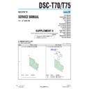
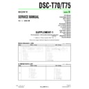
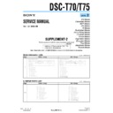
Read Sony DSC-T70 / DSC-T75 (serv.man4) Service Manual online
— 2 —
DSC-T70/T75_L2
Page
5-2. ELECTRICAL PARTS LIST
Before change
After change
5-7
A-1334-226-A ST-172 FLEXIBLE BOARD, COMPLETE
0
1-480-416-11 FLASH UNIT (FL60570)
< LITHIUM BATTERY SECONDARY >
*0BT001
1-756-566-11 BATTERY, LITHIUM SECONDARY
*0C901
1-114-572-11 CAP, ELECT
21.9uF
315V
*0C902
1-114-572-11 CAP, ELECT
21.9uF
315V
< SPEAKER >
* SP901
1-826-759-11 BUZZER, PIEZOELECTRIC (2.0CM)
Ref. No.
Part No.
Description
Ref. No.
Part No.
Description
A-1512-857-A ST-172 FLEXIBLE BOARD, COMPLETE
(SERVICE)
]
)
@
@
@
@
@
@
@
@
@
!
: Deleted portion
-
: Changed portion
&
: Added portion
When soldering, print this sheet and use this as a
workbench for positioning.
workbench for positioning.
Positioning sheet for soldering
the piezoelectric buzzer (SP901)
the piezoelectric buzzer (SP901)
Note: Use this drawing in its actual scale.
If you cannot print this out in its actual scale, the PC
or printer setting is a probable cause.
In such a case, use a photocopier or another tool to
obtain the actual size.
If you cannot print this out in its actual scale, the PC
or printer setting is a probable cause.
In such a case, use a photocopier or another tool to
obtain the actual size.
ST-172 FLEXIBLE BOARD, COMPLETE (SERVICE)
BUZZER, PIEZOELECTRIC
(2.0CM) (SP901)
(2.0CM) (SP901)
cm
0
1
2
3
4
5
6
7
The components identified by mark 0 or
dotted line with mark 0 are critical for safety.
Replace only with part number specified.
dotted line with mark 0 are critical for safety.
Replace only with part number specified.
Les composants identifiés par une marque
0 sont critiques pour la sécurité.
Ne les remplacer que par une pièce portant
le numéro spécifié.
0 sont critiques pour la sécurité.
Ne les remplacer que par une pièce portant
le numéro spécifié.
Display

