Read Sony ZS-D1 Service Manual online
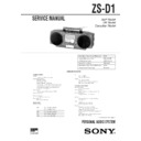
ZS-D1
AEP Model
UK Model
Canadian Model
SERVICE MANUAL
PERSONAL AUDIO SYSTEM
MICROFILM
Model Name Using Similar Mechanism
NEW
Loading Mechanism Type
KSL-213CGP
CD Mechanism Type
KSM-213CGP
Optical Pick-up Name
KSS-213C
Model Name Using Similar Mechanism
NEW
Transport Mechanism Type
MF-ZSD1
SPECIFICATIONS
— Continued on next page —
CD player section
System
Compact disc digital audio system
Laser diode properties
Material: GaAIAs
Wave length: 780nm
Emission duration: Continuous
Laser output: Less than 44.6
Wave length: 780nm
Emission duration: Continuous
Laser output: Less than 44.6
µ
W (This output is the
value measured at a distance of about 200 mm from
the objective lens surface on the optical pick-up
block with 7 mm aperture.)
the objective lens surface on the optical pick-up
block with 7 mm aperture.)
Spindle speed
200 r/min (rpm) to 500 r/min (rpm) (CLV)
Number of channels
2
Frequency response
20 - 20,000 Hz +0.5/-2 dB
Wow and flutter
Below measurable limit
Radio section
Frequency range
FM
87.6 - 107 MHz (AEP, UK)
87.6 - 108 MHz (CND)
MW
531 - 1,602 kHz (AEP, UK)
LW
153 - 279 kHz (AEP, UK)
AM
530 - 1,710 kHz (CND)
IF
FM: 10.7 MHz
MW/LW,AM: 450 kHz
MW/LW,AM: 450 kHz
Aerials
FM: Telescopic aerial
MW/LW: Built-in loop aerial (AEP, UK)
AM: Built-in loop aerial (CND)
MW/LW: Built-in loop aerial (AEP, UK)
AM: Built-in loop aerial (CND)
Cassette-corder section
Recording system
4-track 2 channel stereo
Fast winding time
Approx. 130s (sec.) with Sony cassette C-60
Frequency response
TYPE (normal): 70 - 10,000 Hz
Speaker
Full range: 8 cm (3
1
/
4
in.) dia., 3.2 ohms,
cone type x 2
Input
LINE IN jack (stereo minijack)
Minimum input level 250 mV
Minimum input level 250 mV
Outputs
Headphones jack (stereo minijack)
For 16 - 68 ohms impedance headphones
LINE OUT jack (stereo minijack)
Rated output level 250 mV at load impedance 47
kilohms
Optical digital output (optical output connector)
Wave length: 630 - 690 nm
For 16 - 68 ohms impedance headphones
LINE OUT jack (stereo minijack)
Rated output level 250 mV at load impedance 47
kilohms
Optical digital output (optical output connector)
Wave length: 630 - 690 nm
— 2 —
1.
GENERAL
Parts and controls ········································································· 3
Basic Operations
Basic Operations
Playing a CD ············································································· 4
Listening to the radio ································································ 5
Playing a tape ············································································ 6
Recording on a tape ·································································· 7
Listening to the radio ································································ 5
Playing a tape ············································································ 6
Recording on a tape ·································································· 7
The CD Player
Using the display ······································································ 8
Setting the clock ······································································· 8
Setting the clock ······································································· 8
2.
DISASSEMBLY
2-1.
CABINET (FRONT) ASSY ··············································· 9
2-2.
HANDLE ·········································································· 10
2-3.
JACK CHASSIS ······························································· 10
2-4.
CABINET (UPPER) ASSY ·············································· 11
2-5.
MAIN BOARD ································································ 11
2-6.
MECHANISM DECK SECTION ···································· 12
2-7.
CONTROL BOARD ························································ 12
2-8.
CD SECTION ··································································· 13
2-9.
CD MECHANISM DECK ··············································· 13
2-10. OPTICAL PICK-UP ························································· 14
2-11. ROOP ANTENNA ··························································· 14
2-12. POWER TRANSFORMER ············································· 15
2-11. ROOP ANTENNA ··························································· 14
2-12. POWER TRANSFORMER ············································· 15
3.
TEST MODE
................................................................ 16
4.
MECHANICAL ADJUSTMENTS
.......................... 17
5.
ELECTRICAL ADJUSTMENTS
5-1.
TAPE RECORDER SECTION ········································ 17
5-2.
TUNER SECTION ··························································· 19
5-3
CD SECTION ··································································· 20
5-4.
REFERENCE ··································································· 21
Maximum power output
4.5 W + 4.5 W (at 3.2 ohms, 10 % harmonic
distortion)
distortion)
Power requirements
For personal component system:
230 V AC, 50 Hz (AEP, UK)
120 V AC, 60 Hz (CND)
12V DC, 8 R20 (size D) batteries
For remote commander:
3 V DC, 2 R6 (size AA) batteries
230 V AC, 50 Hz (AEP, UK)
120 V AC, 60 Hz (CND)
12V DC, 8 R20 (size D) batteries
For remote commander:
3 V DC, 2 R6 (size AA) batteries
Power consumption
AC 25 W
Battery life
For CD radio cassette-corder
FM recording
Sony R20P: approx. 4.5 h
Sony alkaline LR20: approx. 12 h
Tape playback
Sony R20P: approx. 2 h
Sony alkaline LR20: approx. 4.5 h
CD playback
Sony R20P: appprox. 2 h
Sony alkaline LR20: approx. 4.5h
TABLE OF CONTENTS
6.
DIAGRAMS
6-1.
IC PIN FUNCTION ························································· 23
6-2.
CIRCUIT BOARDS LOCATION ···································· 25
6-3.
BLOCK DIAGRAM – MAIN SECTION – ··························· 26
6-4.
BLOCK DIAGRAM – TC SECTION – ································ 29
6-5.
BLOCK DIAGRAM – CD SECTION – ································ 31
6-6.
PRINTED WIRING BOARD
– MAIN SECTION (AEP, UK, IT Model) – ···················· 33
– MAIN SECTION (AEP, UK, IT Model) – ···················· 33
6-7.
PRINTED WIRING BOARD
– MAIN SECTION (CND Model) – ································ 38
– MAIN SECTION (CND Model) – ································ 38
6-8.
SCHEMATIC DIAGRAM – MAIN (AUDIO) SECTION – ··· 43
6-9.
SCHEMATIC DIAGRAM – MAIN (RADIO) SECTION – ··· 46
6-10. SCHEMATIC DIAGRAM – MAIN (TC) SECTION – ········ 49
6-11. SCHEMATIC DIAGRAM – MAIN (CD) SECTION – ······· 52
6-12. SCHEMATIC DIAGRAM
6-11. SCHEMATIC DIAGRAM – MAIN (CD) SECTION – ······· 52
6-12. SCHEMATIC DIAGRAM
– MAIN (SYSTEM CONTROL) SECTION – ················ 55
6-13. PRINTED WIRING BOARD – CD SECTION – ················ 58
6-14. SCHEMATIC DIAGRAM – CD SECTION – ······················ 61
6-15. PRINTED WIRING BOARD
6-14. SCHEMATIC DIAGRAM – CD SECTION – ······················ 61
6-15. PRINTED WIRING BOARD
– PANEL SECTION (AEP, UK, IT Model) – ·················· 64
6-16. PRINTED WIRING BOARD
– PANEL SECTION (CND Model) – ······························ 67
6-17. SCHEMATIC DIAGRAM – PANEL SECTION – ··············· 70
6-18. IC BLOCK DIAGRAMS ················································· 73
6-18. IC BLOCK DIAGRAMS ················································· 73
7.
EXPLODED VIEWS
7-1.
FRONT CABINET SECTION ········································· 77
7-2.
REAR CABINET SECTION ··········································· 78
7-3.
UPPER CABINET SECTION ········································· 79
7-4.
MECHANISM DECK SECTION-1 ································ 80
7-5.
MECHANISM DECK SECTION-2 ································ 81
7-6.
MECHANISM DECK SECTION-3 ································ 82
7-7.
MECHANISM DECK SECTION-4 ································ 83
7-8.
CD CHASSIS SECTION ················································· 84
7-9.
OPTICAL PICK-UP SECTION ······································· 85
8.
ELECTRICAL PARTS LIST
................................... 86
Dimensions (incl. projecting parts)
Approx. 440
×
164
×
256 mm (w/h/d)
(17 3/8
×
6
1
/
2
×
10
1
/
8
inches)
Mass (incl. batteries)
Approx. 6 kg (13 lb. 3 oz)
Supplied accessories
AC power cord (1)
Remote commander (1)
Remote commander (1)
Design and specifications are subject to change without
notice.
notice.
Optional accessories
Sony MDR headphone series
— 3 —
SECTION 1
GENERAL
This section is extracted
from instruction manual.
1 6 PUSH (to open the tape compartment) button
(DECK A)
2 FM ANTENNA
3 Tape operating button
3 Tape operating button
9 /( (PLAY)
p (STOP)
0 / ) (FF/REW · AMS)
DUBBING START button
r / P (REC/REC PAUSE)
DECK A/B
p (STOP)
0 / ) (FF/REW · AMS)
DUBBING START button
r / P (REC/REC PAUSE)
DECK A/B
4 CASSETTE LID DECK A/B
5 CD · Radio operationg button
5 CD · Radio operationg button
CD :
^ (PLAY/PAUSE)
p (STOP)
REPEAT
p (STOP)
REPEAT
Radio :
BAND
AUTO PRESET
AUTO PRESET
Common : PLAY MODE/MONO/ST/ISS*
* Decreases the noise while recording AM broadcast
0 / ) SERCH /TUNING
+ / –
* Decreases the noise while recording AM broadcast
0 / ) SERCH /TUNING
+ / –
6 6 PUSH (to open the tape compartment) button
(DECK B)
7 MEGA BASS button
8 SOUND button
9 VOLUME button
!º DISPLAY button
!¡ DIR MODE (to select direction of the tape) button
!™ COUNTER RESET button
!£ 6 OPEN/CLOSE button
9 VOLUME button
!º DISPLAY button
!¡ DIR MODE (to select direction of the tape) button
!™ COUNTER RESET button
!£ 6 OPEN/CLOSE button
!¢ CD tray
!∞ jog dial
!∞ jog dial
CD :
AMS, Program Play, Music selection on EDIT
Radio :
Presetting radio stations
Clock · Timer : Setting the clock, Setting the music source · volume
!§ ENTER button
!¶ CANCEL button
!• OPTICAL DIGITAL OUTPUT (CD)
!¶ CANCEL button
!• OPTICAL DIGITAL OUTPUT (CD)
jack
LINE IN jack
LINE OUT jack
LINE IN jack
LINE OUT jack
!ª PGM SET/MEMORY button
@º CLOCK button
@¡ TIMER button
@™ EDIT button
@£ OPR/BATT indicator
@¢ Remote sensor
@º CLOCK button
@¡ TIMER button
@™ EDIT button
@£ OPR/BATT indicator
@¢ Remote sensor
@∞ LINE button
@§ STANDBY button
@¶ POWER button (CND), OPERATE button (AEP, UK)
@• SLEEP button
@ª PHONES jack (stereo mini jack)
@§ STANDBY button
@¶ POWER button (CND), OPERATE button (AEP, UK)
@• SLEEP button
@ª PHONES jack (stereo mini jack)
— 4 —


