Read Sony TA-FE230 / TA-FE330R / TA-FE530R Service Manual online
SERVICE MANUAL
INTEGRATED STEREO AMPLIFIER
AEP Model
UK Model
SPECIFICATIONS
TA-FE230/FE330R/FE530R
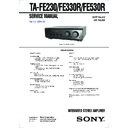
Photo: TA-FE530R (BLACK)
9-928-825-12
Sony Corporation
2001B0500-1
Audio Entertainment Group
C
2001.2
General Engineering Dept.
Ver 1.1 2001.02
– 2 –
TABLE OF CONTENTS
1.
GENERAL
Location of Controls .......................................................
3
2.
DISASSEMBLY
.........................................................
4
3.
DIAGRAMS
3-1. Note for Printed Wiring Boards
and Schematic Diagrams ................................................
7
3-2. Printed Wiring Board – MAIN Section – ......................
9
3-3. Schematic Diagram – MAIN Section – .......................... 11
3-4. Printed Wiring Boards – PANEL Section – .................. 13
3-5. Schematic Diagram – PANEL Section – ....................... 15
3-6. Printed Wiring Boards – POWER Section – ................. 17
3-7. Schematic Diagram – POWER Section – ..................... 19
3-8. IC Pin Function Description ........................................... 22
4.
EXPLODED VIEWS
................................................ 23
5.
ELECTRICAL PARTS LIST
............................... 26
SAFETY-RELATED COMPONENT WARNING!!
COMPONENTS IDENTIFIED BY MARK
!
OR DOTTED
LINE WITH MARK
!
ON THE SCHEMATIC DIAGRAMS
AND IN THE PARTS LIST ARE CRITICAL TO SAFE
OPERATION. REPLACE THESE COMPONENTS WITH
SONY PARTS WHOSE PART NUMBERS APPEAR AS
SHOWN IN THIS MANUAL OR IN SUPPLEMENTS PUB-
LISHED BY SONY.
OPERATION. REPLACE THESE COMPONENTS WITH
SONY PARTS WHOSE PART NUMBERS APPEAR AS
SHOWN IN THIS MANUAL OR IN SUPPLEMENTS PUB-
LISHED BY SONY.
– 3 –
SECTION 1
GENERAL
This section is extracted from
instruction manual.
instruction manual.
LOCATION OF CONTROLS
•
Front View
1
I
/
u button
2 Remote sensor (TA-FE330R/FE530R)
3 EON LINK button and indicator
3 EON LINK button and indicator
(TA-FE530R)
4 PHONES jack
5 SPEAKERS switch
6 BASS dial
7 TREBLE dial
8 BALANCE dial
9 LOUDNESS button
0 INPUT SELECTOR
!¡ SOURCE DIRECT button
5 SPEAKERS switch
6 BASS dial
7 TREBLE dial
8 BALANCE dial
9 LOUDNESS button
0 INPUT SELECTOR
!¡ SOURCE DIRECT button
(TA-FE330R/FE530R)
!™ VOLUME dial
!£ TAPE1 MONITOR switch
!£ TAPE1 MONITOR switch
(TA-FE530R)
1 2
3 4
5 6 7 8 9 !º !¡ !™ !£
•
Rear View
– 4 –
CASE
PANEL ASS’Y
Note:
Follow the disassembly procedure in the numerical order given.
SECTION 2
DISASSEMBLY
1
two screws
(CASE)
(CASE)
1
screw (CASE)
1
two screws
(CASE)
(CASE)
2
case
2
connector (CN7) (FE230)
2
connector (CN903)
(FE330R/FE530R)
(FE330R/FE530R)
3
two clamps
4
screw (BVTP3
×
8)
5
claw
6
panel ass’y
4
three screws
(BVTP3
(BVTP3
×
8)
5
claw
4
screw (BVTP3
×
8)
2
connector (CN812)
(FE530R)
(FE530R)
1
wire (flat type) (13 core)
(CN815)
(CN815)
1
wire (flat type) (13 core)
(CN811)
(CN811)

