Read Sony SRS-T10PC Service Manual online
SERVICE MANUAL
Sony Corporation
Audio&Video Business Group
Published by Sony Techno Create Corporation
Published by Sony Techno Create Corporation
Canadian Model
E Model
Chinese Model
ACTIVE SPEAKER SYSTEM
9-879-466-03
2008I16-1
© 2008.09
© 2008.09
Ver. 1.2 2008.09
SPECIFICATIONS
SRS-T10PC
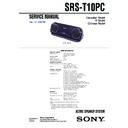
Photo : BLACK
Speaker section
Enclosure type
Full range, Bass reflex,
magnetically shielded
magnetically shielded
Speaker system
39 mm
Impedance
4 Ω
Rated input power
0.25 W
Maximum input power 0.3 W
Amplifier section
Maximum output power 0.25 W + 0.25 W
(10 % T.H.D., 1 kHz, 4 Ω)
Input
USB cable, Type A plug,
Approx. 30 cm (11
Approx. 30 cm (11
7
/
8
inch)
System required
Compliant computer
IBM PC/AT or compatible
computers with USB port
computers with USB port
Compliant OS*
Windows XP Professional,
Windows XP Home Edition,
Windows XP Home Edition,
Windows 2000 Professional
(Canadian, E)
,
Windows Millennium Edition
(Canadian, E)
,
Windows 98 Second Edition
(Canadian, E)
Recommended CPU
Pentium II 300 MHz or faster/
Celeron 500 MHz or faster
Celeron 500 MHz or faster
General
Power supply
USB bus power compliant
(5 V, 500 mA or less)
(5 V, 500 mA or less)
Dimensions (w
×
h
×
d) Approx.
170
×
60
×
24 mm
(6
3
/
4
×
×
2 /
8
31
/
32
inch)
3
Mass
Approx. 190 g (7 oz.)
Supplied accessory
Operating instructions (1)
Design and specifications are subject to change without
notice.
* Complies with the original manufacturer-installed
notice.
* Complies with the original manufacturer-installed
operating system. Trouble-free operations are not
guaranteed for all computers with the above systems
installed.
guaranteed for all computers with the above systems
installed.
Windows Vista Home Basic (Chinese) ,
Windows Vista Home Premium (Chinese) ,
Windows Vista Business (Chinese) ,
Windows Vista Ultimate (Chinese) ,
Windows Vista Home Premium (Chinese) ,
Windows Vista Business (Chinese) ,
Windows Vista Ultimate (Chinese) ,
Windows XP Media Center Edition 2005 (Chinese) ,
Windows 2000 SP4 (Chinese) ,
Windows 2000 SP4 (Chinese) ,
2
SRS-T10PC
TABLE OF CONTENTS
1.
GENERAL
...................................................................
3
2.
DIAGRAMS
2-1.
Printed Wiring Board – AMP Board – ...........................
5
2-2.
Schematic Diagram – AMP Board – ..............................
6
3.
EXPLODED VIEWS
.................................................
8
4.
ELECTRICAL PARTS LIST
..................................
9
Notes on chip component replacement
• Never reuse a disconnected chip component.
• Notice that the minus side of a tantalum capacitor may be
damaged by heat.
UNLEADED SOLDER
Boards requiring use of unleaded solder are printed with the lead-
free mark (LF) indicating the solder contains no lead.
(Caution: Some printed circuit boards may not come printed with
free mark (LF) indicating the solder contains no lead.
(Caution: Some printed circuit boards may not come printed with
the lead free mark due to their particular size)
: LEAD FREE MARK
Unleaded solder has the following characteristics.
• Unleaded solder melts at a temperature about 40 °C higher
than ordinary solder.
Ordinary soldering irons can be used but the iron tip has to be
applied to the solder joint for a slightly longer time.
Soldering irons using a temperature regulator should be set to
about 350
Ordinary soldering irons can be used but the iron tip has to be
applied to the solder joint for a slightly longer time.
Soldering irons using a temperature regulator should be set to
about 350
°C.
Caution: The printed pattern (copper foil) may peel away if
the heated tip is applied for too long, so be careful!
• Strong viscosity
Unleaded solder is more viscou-s (sticky, less prone to flow)
than ordinary solder so use caution not to let solder bridges
occur such as on IC pins, etc.
than ordinary solder so use caution not to let solder bridges
occur such as on IC pins, etc.
• Usable with ordinary solder
It is best to use only unleaded solder but unleaded solder may
also be added to ordinary solder.
also be added to ordinary solder.
3
SRS-T10PC
SECTION 1
GENERAL
This section is extracted
from instruction manual.
from instruction manual.
2
3
Cover
1
Setting the speaker
1
Open the cover.
2
Pull out the USB cable from the system
storage section.
storage section.
3
Stand the speaker on the cover.
Putting the USB cable back in the system
storage section
storage section
See illustration.
4
SRS-T10PC
SECTION 2
DIAGRAMS
Note on Printed Wiring Boards.
•
•
X
: parts extracted from the component side.
•
Y
: parts extracted from the conductor side.
•
: Pattern from the side which enables seeing.
(The other layers' patterns are not indicated.)
NOTE FOR PRINTED WIRING BOARDS AND SCHEMATIC DIAGRAMS.
Caution:
Pattern face side:
Pattern face side:
Parts on the pattern face side seen from
(Side B)
the pattern face are indicated.
Parts face side:
Parts on the parts face side seen from
(Side A)
the parts face are indicated.
• Waveform
Note on Schematic Diagrams.
• All capacitors are in
• All capacitors are in
µ
F unless otherwise noted. (p: pF) 50 WV or
less are not indicated except for electrolytics and tantalums.
• All resistors are in
Ω
and
1
/
4
W or less unless otherwise specified.
•
f
: internal tolerance.
•
C
: panel designation.
•
A
: B+ Line.
• Voltages and waveforms are measured with USB cable connected
with PC.
• Voltages are taken with a VOM (Input impedance 10 M
Ω
).
Voltage variations may be noted due to normal production toler-
ances.
ances.
• Waveforms are taken with a oscilloscope.
Voltage variations may be noted due to normal production toler-
ances.
ances.
• Circled numbers refer to waveforms.
• Signal path.
F
: AUDIO
• IC Block Diagram
1
IC1
8
XI
83.3 ns
3.6 Vp-p
1 V/DIV, 40 ns/DIV
1
2
3
4
5
6
7
8
A.–
A.+
B.+
B.–
A.OUT
B.OUT
VDD
GND
IC2 NJM2073M(TE2)
• Indication of transistor
C
B
These are omitted.
E
Q


