Read Sony HS-RM436 / HS-RM439 Service Manual online
HS-RM436/RM439
SERVICE MANUAL
STEREO RADIO CASSETTE PLAYER
SPECIFICATIONS
E Model
Model Name Using Similar Mechanism
NEW
MD Mechanism Type
MF-HSRM436-114
9-877-337-01
2003E02-1
© 2003.05
Ver 1.0 2003.05
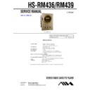
Photo: HS-RM436
Sony Corporation
Personal Audio Company
Published by Sony Engineering Corporation
Frequency range:
AM 531 – 1,602 kHz (9 kHz steps)
AM 530 – 1,710 kHz (10 kHz steps)
FM1, FM2 87.5 – 108 MHz (50 kHz steps)
AM 530 – 1,710 kHz (10 kHz steps)
FM1, FM2 87.5 – 108 MHz (50 kHz steps)
AM tuning step:
E model: 9kHz fixed
9E model: 9kHz/10kHz changeable
9E model: 9kHz/10kHz changeable
Maximum output:
8.0 mW + 8.0 mW (JEITA 32 ohms)
Load impedance:
32 ohms
Power source:
DC 3 V using two R6 (size AA) dry cell batteries
AC house current using the optional AC power adaptor
AC-E30HG
AC house current using the optional AC power adaptor
AC-E30HG
Battery life (JEITA, 0.2 mW output, playback):
Approx. 7 hours using R6P (size AA) manganese batteries
Approx. 25 hours using LR6 (size AA) alkaline batteries
Approx. 25 hours using LR6 (size AA) alkaline batteries
Maximum outside dimensions (W x H x D):
88.3 x 115 x 29.8 mm (excluding projecting parts and controls)
Weight:
Approx. 146 g (excluding batteries)
Accessories:
Stereo headphones (1)
Remote control (1) (RM439)
Belt clip (1)
Remote control (1) (RM439)
Belt clip (1)
The specifications and external appearance of this unit are subject to change without prior notice.
2
HS-RM436/RM439
Specifications ........................................................................... 1
1. GENERAL
...................................................................... 3
2. DISASSEMBLY
2-1. Cabinet (Rear)ASSY .................................................. 4
2-2. Main Board ................................................................. 4
2-3. Mechanism Deck ........................................................ 5
2-4. Belt, Capstan/reel Motor (M601),
Magnetic Head (Playback) (HP601) ........................... 5
2-2. Main Board ................................................................. 4
2-3. Mechanism Deck ........................................................ 5
2-4. Belt, Capstan/reel Motor (M601),
Magnetic Head (Playback) (HP601) ........................... 5
3. ADJUSTMENTS
3-1. Mechanical Adjustments ............................................ 7
3-2. Electrical Adjustments ................................................ 7
3-2. Electrical Adjustments ................................................ 7
4. DIAGRAMS
4-1. Explanation of IC Terminals ..................................... 10
4-2. Block Diagram ........................................................... 11
4-3. Printed Wiring Boards – Main Section (Side A) – ... 12
4-4. Printed Wiring Boards – Main Section (Side B) – ... 13
4-5. Schematic Diagram – Main Section (1/2) – ............. 14
4-6. Schematic Diagram – Main Section (2/2) – ............. 15
5. EXPLODED VIEWS
5-1. Cabinet Section ......................................................... 17
5-2. Mechanism Deck Section
(MF-HSRM436-114) (1/2) ....................................... 18
5-3. Mechanism Deck Section
(MF-HSRM436-114) (2/2) ....................................... 19
5-2. Mechanism Deck Section
(MF-HSRM436-114) (1/2) ....................................... 18
5-3. Mechanism Deck Section
(MF-HSRM436-114) (2/2) ....................................... 19
6. ELECTRICAL PARTS LIST
................................... 20
Flexible Circuit Board Repairing
• Keep the temperature of the soldering iron around 270
°
C during
repairing.
• Do not touch the soldering iron on the same conductor of the
circuit board (within 3 times).
• Be careful not to apply force on the conductor when soldering or
unsoldering.
Notes on chip component replacement
• Never reuse a disconnected chip component.
• Notice that the minus side of a tantalum capacitor may be dam-
• Notice that the minus side of a tantalum capacitor may be dam-
aged by heat.
TABLE OF CONTENTS
3
HS-RM436/RM439
SECTION 1
GENERAL
This section is extracted from
instruction manual.
instruction manual.
LOCATION AND FUNCTION OF CONTROLS
SUPER BASS
ENTER
MODE
PRESET/TUNE
HOLD
VOLUME
AM
FM2
FM1
OFF
STOP
PLAY
N
4
HS-RM436/RM439
SECTION 2
DISASSEMBLY
Note :
Follow the disassembly procedure in the numerical order given.
2-1. CABINET (REAR) ASSY
2-2. MAIN BOARD
• The equipment can be removed using the following procedure.
Main board
Cabinet (Front) ASSY
Cabinet (rear) ASSY
Cassette holder
Mechanism deck
Belt, Capstan/reel motor (M601),
Magnetic head (Playback) (HP601)
Set
2
Claws
3
2
Claws
2
Claws
2
Claws
1
Screw
Cabinet (rear) ASSY
Cabinet (front) ASSY
7
Lid, battery case
5
Claws
Cabinet (front) ASSY
6
4
Screw
3
Screw
2
Remove solder
1
Remove solder
Main board
Note :
Use the precision driver with coverd a point
by cloth to release the claw.
Be careful not to damage claws.
Be careful not to damage claws.


