Read Sharp PZ-50MR2E (serv.man4) Service Manual online
4
PZ-43MR2E
PZ-50MR2E
PZ-50MR2E
Operation Manual
P
B
(C
B
)
COMPONENT
P
R
(C
R
)
Y
R - AUDIO - L
INPUT 3
INPUT 2
INPUT 1
RS-232C
DISPLAY OUTPUT-1
DISPLAY OUTPUT-2
AC INPUT
220–240V
220–240V
AV OUTPUT
S-VIDEO
VIDEO
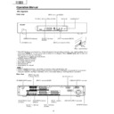
Front view
INPUT 1 terminal
(SCART)
(SCART)
INPUT 3 terminals
(Y, P
(Y, P
B
(C
B
)
,
P
R
(C
R
))
INPUT 2 terminal
(SCART)
(SCART)
AV OUTPUT terminal
(S-VIDEO)
(S-VIDEO)
DISPLAY OUTPUT-1 terminal
AC INPUT terminal
CLEAR button
*
POWER button
RS-232C terminal
INPUT 4 terminal (S-VIDEO)
INPUT 4 terminal (VIDEO)
PC INPUT terminal
(AUDIO)
(AUDIO)
INPUT 4 terminals (AUDIO)
INPUT 3 terminal (SCART)
AV OUTPUT terminal
(VIDEO)
(VIDEO)
AV OUTPUT terminals
(AUDIO)
(AUDIO)
PC INPUT terminal (ANALOG RGB)
* If the AVC System is switched on but it does not appear to be operating correctly, it may need resetting. In this
case press
CLEAR
on the front of the unit as shown in the diagram. Press
CLEAR
lightly with the end of a
ballpoint pen or other pointed object.
This will reset the System as shown below.
This will reset the System as shown below.
• AV MODE resets to STANDARD
• TV channel resets to channel 1
• Dual screen resets to normal
• Audio setting initialises
• SRS resets to Off
• Image position is initialised
• TV channel resets to channel 1
• Dual screen resets to normal
• Audio setting initialises
• SRS resets to Off
• Image position is initialised
A
• Pressing
• Pressing
CLEAR
will not work if the System is in standby mode (indicator lights red).
• Pressing
CLEAR
will not delete channel preset or password. See Page for initialising factory preset settings when you
know your password. See Page or initialising factory preset values when you have forgotten your password.
Rear view
ANTENNA INPUT terminal
AVC System
STANDBY/ON indicator
DISPLAY OUTPUT-2 terminal
Door knob
(How to open the door)
5
PZ-43MR2E
PZ-50MR2E
PZ-50MR2E
1
a
(STANDBY/ON)
To switch the power on and off.
2
du
(FREEZE/HOLD for TELETEXT)
TV/External input mode: Change the still image mode.
TELETEXT mode: Freeze a multi-page on screen while other
pages are automatically updated. Press d again to return to the
normal image.
TELETEXT mode: Freeze a multi-page on screen while other
pages are automatically updated. Press d again to return to the
normal image.
3
c
(DUAL screen)
Set the dual picture mode. Press c again to return to normal view.
4
fv
(WIDE MODE/ T/B/F)*
TV/External input mode: Change the wide image mode.
TELETEXT mode: Set the area of magnification. (full/upper half/
lower half)
TELETEXT mode: Set the area of magnification. (full/upper half/
lower half)
5
AV MODE*
Select a video setting. AV MODE (STANDARD, DYNAMIC, MOVIE,
GAME, USER) PC MODE (STANDARD, USER)
GAME, USER) PC MODE (STANDARD, USER)
6
SOUND
Select the sound multiplex mode.
7
h
(SRS and FOCUS)
Select SRS and FOCUS Sound System.
8
A
(FLASHBACK)
Press to return to the previous channel in normal viewing mode.
Press to return to the previous page in TELETEXT mode.
Press to return to the previous page in TELETEXT mode.
9
il/ik
(VOLUME)*
Set the volume.
10
(Reveal hidden for TELETEXT)
TELETEXT mode: Display hidden characters.
11
j
(SUBPAGE for TELETEXT)
TELETEXT mode: Change the picture mode for sub-page selecting.
12
MENU
Display the Menu screen.
13
C
(CHANNEL INFORMATION)
Display the channel information and time.
14
b
(INPUT SOURCE)
Select an input source. (TV, INPUT 1, INPUT 2, INPUT 3, INPUT 4,
PC)
PC)
15
SLEEP
Set the SLEEP TIMER.
16
e
(MUTE)
Mute the sound.
17
0 – 9
TV/External input mode: Set the channel.
TELETEXT mode: Set the page.
TELETEXT mode: Set the page.
18
o
(Digit for channel select)
Change the digits of the selected TV channel.
19
Colour (RED/GREEN/YELLOW/BLUE)
TELETEXT mode: Select a page.
20
CH
a/
CH
b(w/x
)
TV/External input mode: Select the channel.
TELETEXT mode: Set the page.
TELETEXT mode: Set the page.
21
l
(TOP Overview for TELETEXT)
TELETEXT mode: Display an index page for CEEFAX/FLOF
information. TOP OVER VIEW for TOP programme.
information. TOP OVER VIEW for TOP programme.
22
m
(TELETEXT)
Select the TELETEXT mode. (all TV image, all TEXT image, TV/TEXT
image)
image)
23
RETURN
MENU mode: Return to the previous menu screen.
24
ENTER
Execute a command.
Return to the initial image position after moving with a/b/c/d.
Return to the initial image position after moving with a/b/c/d.
25
a/b/c/d
(Cursor)
Select a desired item on the setting screen.
Move the picture on the screen.
Move the picture on the screen.
1
2
3
4
5
6
7
8
9
2
3
4
5
6
7
8
9
10
11
12
11
12
14
15
15
13
16
17
18
19
19
20
21
22
23
24
21
22
23
24
25
Remote control unit
A
• When using the remote control unit, point it
• When using the remote control unit, point it
at the Plasma Display TV (Panel Unit).
*
“TV”, “INPUT1”, “INPUT2”, “INPUT3”,
“INPUT4” and “PC” modes can each store
the WIDE mode setting separately.
The same for AV mode and volume.
“INPUT4” and “PC” modes can each store
the WIDE mode setting separately.
The same for AV mode and volume.
k
6
PZ-43MR2E
PZ-50MR2E
PZ-50MR2E
Preparation
P
B
(C
B
)
COMPONENT
P
R
(C
R
)
Y
R - AUDIO - L
INPUT 3
INPUT 2
INPUT 1
RS-232C
DISPLAY OUTPUT-1
DISPLAY OUTPUT-2
AC INPUT
220–240V
220–240V
AV OUTPUT
S-VIDEO
VIDEO
System cable
AVC System (rear view)
Power cord
Plasma Display TV (Panel Unit) (rear view)
Power cord
System cable
(bottom view)
(GRAY)
(WHITE)
(GRAY)
(WHITE)
Setting the system
1.
Connecting the system cable, the power cord and the speaker cables to the Plasma Display TV (Panel
Unit)
2.
Connecting the system cable and the power cord to the AVC System
L
• TO PREVENT RISK OF ELECTRIC SHOCK, DO NOT TOUCH UN-INSULATED PARTS OF ANY CABLES WITH THE
POWER CORD CONNECTED.
Speaker cables
(GRAYeGRAY with white stripe)
Speaker cable
Speaker cable
As you apply pressure to this part,
insert the speaker cable. It is
important to match polarity when
connecting the speaker cables to the
terminals.
insert the speaker cable. It is
important to match polarity when
connecting the speaker cables to the
terminals.
Insert the speaker cable
Lift up the snap clip.
Insert the wire into
the hole of the
connector.
the hole of the
connector.
Lower the snap clip
to grip the wire in
place.
to grip the wire in
place.
Black
Red
Black
Red
A
• Two speaker cables of different lengths are supplied. As
• Two speaker cables of different lengths are supplied. As
shown in the diagram, connect the longer speaker cable
to the left speaker and the shorter to the right.
to the left speaker and the shorter to the right.
7
PZ-43MR2E
PZ-50MR2E
PZ-50MR2E
preparation
As viewed from the rear of the display.
How to route cables
A system cable clamp and five speaker cable clamps are included with the system for cable management. Follow the
diagram below for correct cable management.
diagram below for correct cable management.
System cable
Wedge the power cord and the
system cable into the groove on the
stand.
system cable into the groove on the
stand.
Power cord
Speaker cable
Stick the speaker cable clamps
(2 – 4) to the surface as shown.
(2 – 4) to the surface as shown.
System cable clamp
Speaker cable clamp
Speaker cable clamp
System cable
System cable clamp

