Read Sharp LC-40LU700E (serv.man7) Service Manual online
LC-32/40/46LE700E/RU/S,LU700E/S,LX700E/RU,LC-52LE700E/RU/S
4 – 1
LC32LE700E
Service Manual
CHAPTER 4.
REMOVING OF MAJOR PARTS
[1] REMOVING OF MAJOR PARTS
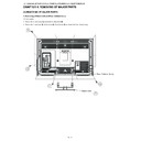
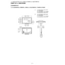
1. Removing of Stand Unit and Rear Cabinet Ass’y.
(32 inch models)
1. Remove the 4 lock screws
and detach the Stand Unit .
2. Remove the 1 lock screw
, 4 lock screws , 8 lock screws
and detach the Rear Cabinet Ass’y.
䎔
䎖
䎘
䎗
䎕
䎶䏗䏄䏑䏇䎃䎸䏑䏌䏗
䎵䏈䏄䏕䎃䎦䏄䏅䏌䏑䏈䏗䎃䎤䏖䏖䎊䏜
LC-32/40/46LE700E/RU/S,LU700E/S,LX700E/RU,LC-52LE700E/RU/S
4 – 2
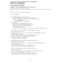
(40/46/52 inch models)
3. Remove the 4 lock screws and detach the Stand Unit
.
4. Remove the 1 lock screw
, 5 lock screws
, 6 lock screws and detach the Rear Cabinet Ass’y.
䎙
䎛
䎔䎓
䎜
䎚
䎶䏗䏄䏑䏇䎃䎸䏑䏌䏗
䎵䏈䏄䏕䎃䎦䏄䏅䏌䏑䏈䏗䎃䎤䏖䏖䎊䏜
LC-32/40/46LE700E/RU/S,LU700E/S,LX700E/RU,LC-52LE700E/RU/S
4 – 3
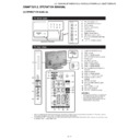
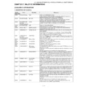
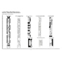
2. Removing of Side Terminal Angle Ass’y, Main PWB Shield, Speaker-L/R and Bottom Cover Ass’y.
1. Detach the Side Terminal Angle Ass’y
.
2. Remove the 4 lock screws
, 1 lock screw
, 4 lock shafts
and 5 lock screws
and detach the Main PWB Shield
.
3. Disconnect SP wire.
4. Detach the Speaker-L
, Speaker-R
.
5. Remove the 2 hooks and detach the Bottom Cover Ass’y
.
䎶䎳
䎘
䎖
䎗
䎙
䎕
䎰䏄䏌䏑䎃䎳䰣䰎䙤䎶䏋䏌䏈䏏䏇
䎕
䎔 䎶䏌䏇䏈䎃䎷䏈䏐䏌䏑䏄䏏䎃
䎤䏑䏊䏏䏈䎃䎤䏖䏖䎊䏜
䎶䏓䏈䏄䏎䏈䏕䎐䎵
䎶䏓䏈䏄䏎䏈䏕䎐䎯
䎛
䎚
䎥䏒䏗䏗䏒䏐䎃䎦䏄䏙䏈䏕䎃䎤䏖䏖䎊䏜 䎜
䎶䎳
Hook
Hook
LC-32/40/46LE700E/RU/S,LU700E/S,LX700E/RU,LC-52LE700E/RU/S
4 – 4
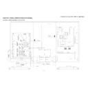
3. Removing of Connectors, R/C, LED Unit, ICON Unit and Control Button Ass’y.
1. Disconnect the following connectors from the MAIN Unit. (RA, LB, PD, KM, LP, LW)
2. Disconnect the following connectors from the POWER Unit. (PD, PL, LB, AS LA1, LA2, LA3 (except for 32/40 inch models))
3. Disconnect the following connectors from the LCD Control Unit. (LP, LW, PL)
4. Detach the R/C, LED Unit
.
5. Detach the ICON Unit
.
6. Disconnect the following connectors from the R/C, LED Unit. (RA, IM)
7. Disconnect the following connector from the ICON Unit. (IM)
8. Detach the Control Button Ass’y
.
9. Disconnect the KEY Unit
from the Control Button Ass’y
and disconnect the connection cord from the KM Connector.
䎮䎰
䰘䰎
䰘䰜
䰜䰐
䎵䎤
䎬䎰
䎵䎤
䎮䎰
䰘䰜
䰜䰘
䰘䰣
䰘䰣
䰜䰘
䰜䰐
䰘䰎
䎬䎰
䎮䎨䎼䎃䎸䏑䏌䏗
䎦䏒䏑䏗䏕䏒䏏䎃䎥䏘䏗䏗䏒䏑
䎤䏖䏖䎊䏜
䎤䏖䏖䎊䏜
䎗
䎖
䎵䎒䎦䎏䎃䎯䎨䎧䎃䎸䏑䏌䏗
䎬䎦䎲䎱䎃䎸䏑䏌䏗
䎔
䎕
䰘䎤䎔
䰘䎤䎕
䰘䎤䎖
䰘䎤䎖
䎤䎶
䎤䎶
䎖䎕䎒䎗䎓䎃䏌䏑䏆䏋䎃䏐䏒䏇䏈䏏䏖
䎖䎋䎕䎃䏌䏑䏆䏋䎃䏐䏒䏇䏈䏏䏖䎌
䎋䎖䎕䎃䏌䏑䏆䏋䎃䏐䏒䏇䏈䏏䏖䎌
䎋䎗䎓䎒䎗䎙䎒䎘䎕䎃
䏌䏑䏆䏋䎃䏐䏒䏇䏈䏏䏖䎌
䎋䎗䎓䎒䎗䎙䎒䎘䎕䎃
䏌䏑䏆䏋䎃䏐䏒䏇䏈䏏䏖䎌
䏈䏛䏆䏈䏓䏗

