Read Sharp LC-37GE1E (serv.man5) Service Manual online
LC-37GE1E
5 – 1
LC-37GE1E
Service Manual
CHAPTER 5.
REMOVING OF MAJOR PARTS
[1] REMOVING OF MAJOR PARTS
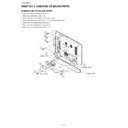
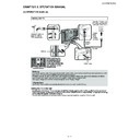
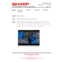
1. Remove the stand cover fixing screws (2 pcs.).
2. Remove the stand fixing screws (4 pcs.).
3. Remove speaker wire L and R from the speaker L and R.
4. Remove the Speaker Box fixing screws (4 pcs.), detach the Speaker Box.
5. Remove the Rear Cabinet fixing screws (3 pcs.).
6. Remove the Rear Cabinet fixing screws (5 pcs.)
7. Remove the Rear Cabinet fixing screws (11 pcs.).
Stand
Stand Cover
1
2
4
5
6
7
3
3
Speaker Wire-R
Speaker Wire-L
Speaker Box
7
LC-37GE1E
5 – 2
8. Detach the Gasket Sld Up/Mid and Electric Tape.
9. Disconnect all the connectors from all the PWBs.
10.Remove the Fan Angle (L) and Vesa Fan Ass’y fixing screws (7 pcs.), detach the Fan Angle (L).
11.Remove the Vesa Fan Ass’y fixing screws (2 pcs.), detach the Vesa Fan Ass’y and Fan Angle (R).
12.Disconnect all the connectors from all the PWBs.
8
10
9
9
10
11
12
12
12
P705
P153
CN2 CN1
P706
SP-L
LB
LA
SP-R
RA
12
12
Fan Angle (L)
Fan Angle (R)
Gasket Sld Up
Gasket Sld Mid
Electric Tape
Vesa Fan Ass'y
LC-37GE1E
5 – 3
13.Remove the Chassis Frame fixing screws (5 pcs.).
14.Remove the Speaker (L) and (R) fixing screws (4 pcs).
15.Remove the LCD Under Angle (L) fixing screw (1 pc.).
16.Remove the LCD Under Angle (L) fixing screws (3 pcs.).
17.Remove the Key PWB fixing screws (5 pcs.).
18.Remove the R/C, LED PWB fixing screws (2 pcs.).
14
14
16
15
18
16
Speaker (L)
17
Speaker (R)
R/C, LED PWB
LCD Under Angle (L)
Key PWB
LC-37GE1E
5 – 4
19.Remove the AV Shield Case fixing screws (4 pcs.).
20.Remove the AV Shield Case fixing screws (4 pcs.).
21.Remove the AV Shield Case Angle and Main PWB and AV PWB fixing screws (5 pcs.).
22.Remove the AV Shield Case Angle fixing screws (3 pcs.).
23.Remove the Tuner PWB fixing screws (3 pcs.).
24.Remove the Digital PWB Shield and Main PWB fixing screws (4 pcs.).
25.Remove the Digital PWB and Digital PWB Shield fixing screws (3 pcs.).
26.Remove the Power PWB fixing screws (7 pcs.).
27.Remove the AV PWB fixing screws (4 pcs.).
13
19
20 23
24
25
26
22
21
27
AV PWB
Main PWB
Tuner PWB
Digital PWB
Digital PWB
Shield
Shield
AV Shield Case
AV Shield
Case Angle
Case Angle
Power PWB
Chassis Frame

