Read Sharp LC-37GD1E (serv.man8) Service Manual online
24
LC-32GD1E
LC-37GD1E
LC-37GD1E
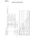
TROUBLE SHOOTING TABLE
No picture and no sound
Is the power LED lit green?
Is the power LED flashing red?
Did it flash once?
Did it flash twice?
Did it flash five times?
Did it flash six times?
Go to "No video output".
Does the backlight fail to light?
Go to "The backlight does not light".
Is the power cord normal?
Replace the power cord.
Go to "The backlight does not light."
Check the power unit.
Check the temperature of the unit.
Check the fan connection.
Does "LOSS OF SYNC" appear?
(
when the monitor alone is operated
)
Check the TMDS RX PWB and its
peripherals.
Ye
s
No
No
No
No
No
No
No
Ye
s
Ye
s
Ye
s
Ye
s
Ye
s
Ye
s
No
Ye
s
T
ype of error
LED operation (1 cycle)
Cable error
A
VC power error
Flashes once: Slow
H: Lit
L: Not lit
Lamp error
Flashes once: Fast
H: Lit
L: Not lit
Monitor power error
Flashes twice
H: Lit
L: Not lit
Monitor temperature
error
H: Lit
L: Not lit
Monitor F
AN error
Flashes 6 times
H: Lit
L: Not lit
LED flashing timing chart
250ms
1s
25
LC-32GD1E
LC-37GD1E
LC-37GD1E
A
data bit is missing.
When the P
A
TTERN 1 setting in the
adjustment process menu is changed
from 00 to 02 is the gradation pattern
displayed correctly?
Connect SC4651 and
SC4652(P
ANEL), and check the
IC4501(LCD-CONT) peripheral
circuit.
When P
A
TTERN1 is selected from
the adjustment process menu and
P
A
TTERN3 is set to 1, is the
gradation pattern displayed
correctly?
Check IC4702, IC4902(64M-
SDRAM), and their peripheral
circuits.
When P
A
TTERN3 in the adjustment
process menu is set to 4, is the
pattern correctly displayed with
even dot signals?
Check between IC4701 and
IC4501(QS-DRIV).
When P
A
TTERN3 in the adjustment
process menu is set to 5, is the
pattern correctly displayed with odd
dot signals?
Check the IC2206 peripheral circuit.
Check between IC4901(QS-DRIV)
and IC4501(LCD-CNT).
No
Ye
s
No
Ye
s
No
Ye
s
Ye
s
No
When the QS driver is activated,
noise is seen in the images.
Check IC4701(QS-DRIV),
IC4901(QS-DRIV), and the
peripheral circuits.
Are the INVER
TER-A
GND PWB
and the LCD CONT
PWB properly
connected with a cable?
(GV
-
Connector)
Is the OSTEMP
AD value on other
Page 2 of the process adjustment
mode set to 255?
Connect them properly or replace
the cable.
Are the INVER
TER-A
GND PWB
and the INVER
TER-B GND PWB
properly connected with a board-to-
board connector? (GJ-Connector)
Connect them properly
.
Is 5V present at pin 62 (OSTEMP)
on IC2004 (the microcomputer)?
The thermistor on the INVER
TER
GND PWB is defective.
Pin 62 on IC2004 (the micro
computer)is defective.
No
Ye
s
No
Ye
s
No
Ye
s
Ye
s
No
26
LC-32GD1E
LC-37GD1E
LC-37GD1E
The display is entirely whitish or
dark. (LCD power)
When the
A
VC system is connected
and the picture is checked, is the
display all white or all black?
Check the
A
VC system.
Check the supply voltage supplied
to the panel.
(Check it at SC4651 and SC4652.)
(VGH,VGL,VLS,VSH)
Remove the FPC that is connected
to SC4651 and SC4652.
(T
o prevent the panel from breaking)
When the P
A
TTERN 1 setting in the
adjudtment process menu is
changed from 00 to 02, is the
gradation pattern displayed
correctly?
(Is it too light or too dark?)
Ye
s
Ye
s
No
No
The backlight does not light.
Has the fuse for F7401 or F7501(32")
F7503(37") on the INVER
TER PWB blown?
Check the circuits after replacing
the fuse.
Is power supplied to each
INVER
TER
PWB?
Is the control signal (OFL1/2, INV
-
OSC) being output at pins 3, 4, and
5 of BL(P7705) on the LCD CONT
PWB?
Check the fluorescent lamp
connector and the inverter circuit.
See if the cable is connected
between PWBs.
Check the IC4501 (LCD-CONT)
peripheral circuits.
Ye
s
Ye
s
Ye
s
Ye
s
No
No
No
27
LC-32GD1E
LC-37GD1E
LC-37GD1E
No video output (Display)
TMDS-RX:
Is RESET terminal at pin (3) of
IC2206 (TMDS-RX) at "H" level?
TMDS-RX:
Is CLOCK (91.3MHz) output
available at pin (102) of IC2206
(TMDS-RX)?
LCD CONT UNIT:
Is CLOCK output available at pin
(40) of IC4602 (LVDS-RX)?
TMDS-RX:
See if X2201 (16.71MHz) leading to
pin (161) of IC2206 is oscillating.
Also check the peripheral circuits.
TMDS-RX:
Check the peripheral circuits of
IC2206 (TMDS-RX).
Check the FFC (LV) connection
between TMDS-RX PWB and LCD
CONT PWB.
Check the peripheral circuits of
IC4501 (LCD CONT).
LCD CONT UNIT:
Check IC4701 (QS-DRIV), IC4901
(QS-DRIV) and the peripheral
circuits.
Is the adjustment process mode
menu displayed?
No audio output (Display)
Is audio signal available at
DISPLAY OUTPUT3 connector
(J2201)?
Is audio signal available at SO
connector (P2201)?
Is audio signal available at SO
connector (P202)?
Check if AVC Center is generating
audio output.
Check the connection between
J2201 and SO connector.
Check SO connector (P202).
Replace if necessary.
Correct the wiring, or replace the
wire.
Check the wire connections in the
speaker assembly.
Is audio signal available in the
speaker assembly?
Replace the speaker, or check the
peripheral connections.
Is speaker wired to audio output
terminal (P203) correctly?
No
No
No
No
Ye
s
Ye
s
Ye
s
Ye
s
No
No
No
No
No
Ye
s
Ye
s
Ye
s
Ye
s
Ye
s

