Read Sharp LC-32GD1E (serv.man7) Service Manual online
17
LC-32GD1E
LC-37GD1E
LC-37GD1E
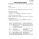
ADJUSTMENT PROCEDURES
The adjustment values are set to the optimum conditions at the factory before shipping. If a value should become
improper or an adjustment is required due to part replacement, make an adjustment according to the following
procedure.
improper or an adjustment is required due to part replacement, make an adjustment according to the following
procedure.
(On The Display)
1. Preparation
When replacing the E2PROM IC (IC2202, IC2208), please note that it must be replaced by a unit.
Applicable unit: DUNTKC268VJ18
Applicable unit: DUNTKC268VJ18
2. Adjusting procedure
Entering the adjustment process mode
→
COM BIAS adjustment
→
White balance adjustment (described in the
AVC section)
3. Entering the adjustment process mode
• Connect the AVC and the display using a system cable.
• Turn OFF the display main power ( ).
• While the main power to the display is off, hold down the “P(
• Turn OFF the display main power ( ).
• While the main power to the display is off, hold down the “P(
Ù
)” key and “ (+)” key on the upper
part of the display and then turn the “MAIN POWER” switch “ON”. The display will run in the “Display
process mode”.
process mode”.
(“<K>” is displayed in the upper left portion of the screen.)
• Then, pressing any key (
• Then, pressing any key (
, P or INPUT) will bring you to the first page of the “Display Adjustment” mode.
Multiple lines of red characters appearing on the display indicate that the unit is now in the adjustment process
mode.
mode.
4. Exiting the adjustment process mode
• To exit the adjustment process mode after the adjustment is done, unplug the AC power cable from the outlet to
make a forced shutdown. Do not use the remote controller or the MAIN POWER switch to exit the mode.
(When the power was turned off with the remote controller, once unplug the power cable and plug it again. In this
case, wait 10 seconds or so before plugging.)
make a forced shutdown. Do not use the remote controller or the MAIN POWER switch to exit the mode.
(When the power was turned off with the remote controller, once unplug the power cable and plug it again. In this
case, wait 10 seconds or so before plugging.)
Key
Cursor UP
Cursor UP
'
Cursor DOWN
"
Cursor RIGHT
û
Cursor LEFT
Û
OK
INPUT
P_UP
P_UP
P(
ù
)
P_DOWN
P(
Ù
)
VOL_UP (+)
VOL_DOWN
(–)
Function 1 (when on the left side of a page)
Moving up by one item or moving to the
previous page (when at the top)
Moving down by one item or moving to the next
page (when at the bottom)
Moving to the right by one item or moving to
another page (in the case of the initial page)
Moving to the left by one item or moving to
another page (in the case of the initial page)
Test pattern off
Moving to the next page
Moving up by one item or moving to the
previous page (when at the top)
Moving down by one item or moving to the next
page (when at the bottom)
Moving to the right by one item or moving to
another page (in the case of the initial page)
Moving to the left by one item or moving to
another page (in the case of the initial page)
Function 2 (when changing a numeric value)
Incrementing the adjustment value by one or
executing the item (in the case of W or R items)
Decrementing the adjustment value by one or
executing the item (in the case of W or R items)
Moving to the right by one item
Incrementing the adjustment value by one or
executing the item (in the case of W or R items)
Decrementing the adjustment value by one or
executing the item (in the case of W or R items)
Moving to the right by one item
Moving to the left by one item
Executing the item (in the case of W or R items)
Moving to the next page
Incrementing the adjustment value by one or
executing the item (in the case of W or R items)
Decrementing the adjustment value by one or
executing the item (in the case of W or R items)
Moving to the right by one item
Incrementing the adjustment value by one or
executing the item (in the case of W or R items)
Decrementing the adjustment value by one or
executing the item (in the case of W or R items)
Moving to the right by one item
Moving to the left by one item
5. Adjustment process mode key operation table
18
LC-32GD1E
LC-37GD1E
LC-37GD1E
6. Adjustment
6-1. COM BIAS adjustment
6-1. COM BIAS adjustment
Shift to the “COM BIAS” item with the cursor
'
/
"
key and select a numeric value with the cursor
Û
/
û
key.
Changing the numeric value with the cursor
'
/
"
key will make appear the test pattern. Make an adjustment
so that the flicker near the center of the screen is minimized.
Adjust each of the ones, tens and hundreds places so that the flicker is minimized.
Adjust each of the ones, tens and hundreds places so that the flicker is minimized.
6-2. White balance adjustment
The way to enter the adjustment process mode is different. Please refer to the description given for the AVC
unit.
unit.
7. Adjusting procedure by use of RS-232C
• Get ready the PC with COM port (RS-232C) running on Windows 98/98SE/ME/2000/XP operating system,
as well as the RS-232C cross cable.
• Start the unit with the RS-232C cable connected.
• Start the terminal software.
(The freeware readily available on the Internet will do.)
• Make the following settings.
as well as the RS-232C cross cable.
• Start the unit with the RS-232C cable connected.
• Start the terminal software.
(The freeware readily available on the Internet will do.)
• Make the following settings.
Baud rate
9600
Data
8 bits
Parity
None
Stop bit
1 bit
Flow control Not implemented
• If the settings are correct, the terminal software indicates “ERR” against pressing of the “ENTER” key.
• After the settings are done correctly, it is possible to make an adjustment by typing in the command shown in
the table below and pressing the “ENTER” key on the keyboard.
Command entry is successful if the terminal software indicates “OK” when the “ENTER” is pressed.
If “ERR” is shown, retry to enter the command.
8. RS232C command table
Command
Function
Remarks
MSET1001
Starting the white balance adjustment
Ending the adjustment with a numeric value other than 1001
MOFR
∗ ∗ ∗ ∗
Adjusting the R GAMMA L value
Range: 0000~0255
MOFG
∗ ∗ ∗ ∗
Adjusting the G GAMMA L value
Range: 0000~0255
MOFB
∗ ∗ ∗ ∗
Adjusting the B GAMMA L value
Range: 0000~0255
MGAR
∗ ∗ ∗ ∗
Adjusting the R GAMMA H value
Range: 0000~0255
MGAG
∗ ∗ ∗ ∗
Adjusting the G GAMMA H value
Range: 0000~0255
MGAB
∗ ∗ ∗ ∗
Adjusting the B GAMMA H value
Range: 0000~0255
MINF0000
Displaying the R GAMMA table
MINF0001
Displaying the G GAMMA table
MINF0002
Displaying the B GAMMA table
table of contents of process mode page 0
Adjust each of the ones, tens and
hundreds places so that the flicker
is minimized.
hundreds places so that the flicker
is minimized.
SERVICE S
→
GRAYLEVEL
COMBIAS
VLSBIAS
L ERR RESET
LCD
PATTERN
MOTOR AND FAN
OTHER
VER M301
VLSBIAS
L ERR RESET
LCD
PATTERN
MOTOR AND FAN
OTHER
VER M301
32/37GD1E
100
155
041
0
100
155
041
0
CEEPD
19
LC-32GD1E
LC-37GD1E
LC-37GD1E
9.Lamp error detection
9-1.Feature description
9-1.Feature description
This liquid-crystal colour TV incorporates a lamp error detection feature (lamp error detection) that automatically
turns OFF the power for safety under abnormal lamp or lamp circuit conditions.
If anything is wrong with the lamp or lamp circuit or when the lamp error detection feature is activated for some
reason, the following will result.
turns OFF the power for safety under abnormal lamp or lamp circuit conditions.
If anything is wrong with the lamp or lamp circuit or when the lamp error detection feature is activated for some
reason, the following will result.
1
The power of TV main body is turned OFF about six seconds after it is turned ON. (The power LED on
the front of the TV turns red from green and keeps blinking in red (ON for 250ms and OFF for 1sec).)
the front of the TV turns red from green and keeps blinking in red (ON for 250ms and OFF for 1sec).)
2
If
1
occurs five times consecutively, it becomes impossible to turn ON the power. (The power LED
keeps blinking in red (ON for 250ms and OFF for 1sec).)
9-2.Measures
1).Checking with lamp error detection OFF
While the “MAIN POWER” switch is off, hold down the “CH(
Ù
)” and “VOL(+)” keys and then turn the “MAIN
POWER” on. The display will run in the “Display process mode” (“<K>” will appear.).
If there is a problem with a lamp or a lamp circuit, the lamp will go out. (The power LED is green.)
Then, you can check the operation to see if the lamp and lamp circuit are abnormal.
Then, you can check the operation to see if the lamp and lamp circuit are abnormal.
2).Resetting the lamp error count
After you have finished checking whether the lamp and lamp circuit are abnormal, reset the lamp error
count. If a lamp error is detected five consecutive times, the power cannot be turned on.
count. If a lamp error is detected five consecutive times, the power cannot be turned on.
Therefore, move to the “L ERR RESET” line, the fourth line on the first page of the“Display adjustment
mode”, using the “Cursor UP/DOWN” key. Then, reset the “L ERR RESET” value using the “Cursor LEFT/
RIGHT” key.
In this case, press the “Cursor UP/DOWN” key to reset it to "0".
mode”, using the “Cursor UP/DOWN” key. Then, reset the “L ERR RESET” value using the “Cursor LEFT/
RIGHT” key.
In this case, press the “Cursor UP/DOWN” key to reset it to "0".
Then perform operation checking and check that the lamp error detection feature is not activated.
First page of the display ajustment process
Normal values of individual displays
Reset to "0"
SERVICE S
GRAYLEVEL
COMBIAS
VLSBIAS
L ERR RESET
LCD
PATTERN
MOTOR AND FAN
OTHER
VER M301
GRAYLEVEL
COMBIAS
VLSBIAS
L ERR RESET
LCD
PATTERN
MOTOR AND FAN
OTHER
VER M301
32/37GD1E
100
155
041
0
100
155
041
0
CEEPD
20
LC-32GD1E
LC-37GD1E
LC-37GD1E
Table of contents of process mode Page 0
LCD Page 5
LCD Page 6
SERVICE S
32/37GD1E
→GRAYLEVEL
1 0 0
COMBIAS
1 5 5
VLSBIAS
0 4 1
L ERR RESET
0
LCD
PATTERN
M O T O R AND FAN
OTHER
VER M301 CEEP D
PATTERN
M O T O R AND FAN
OTHER
VER M301 CEEP D
LCD6
→V H
→V H
0
0 1 5 8
V L
0
0 9 3 8
V H
3 1
0 4 1 8
V L
3 1
0 6 8 6
V H
6 3
0 4 5 2
V L
6 3
0 6 1 9
V H
9 5
0 5 0 3
V L
9 5
0 5 9 0
LCD6
→V H
→V H
1 2 7
0 5 2 1
V L
1 2 7
0 5 4 2
V H
1 5 9
0 5 6 8
V L
1 5 9
0 4 9 7
V H
1 9 1
0 6 1 8
V L
1 9 1
0 4 4 5
V H
2 4 7
0 9 1 4
V L
2 4 7
0 1 3 3
LCD Page 1
LCD Page 2
LCD Page 3
LCD3
→OPC 0
→OPC 0
0 0
OPC 1
05
OPC 2
09
OPC 3
1 3
OPC 4
1 8
OPC 5
2 2
OPC 6
2 7
OPC 7
3 1
OPC 8
3 6
LCD2
→MODE PC
→MODE PC
0
QS SW
0
QS D1
0 8 2
QS D2
1 0 0
QS D3
1 1 1
QS D4
1 2 3
QS D5
1 3 5
QS D6
1 4 7
QS D7
1 6 2
LCD1
→MODE PC 0
PWMCTRL
→MODE PC 0
PWMCTRL
7
PWMFREQ 1 2 8 9
PWMDUTY 1 0000
PWMDUTY 2 0000
PHASEDIF
PWMDUTY 1 0000
PWMDUTY 2 0000
PHASEDIF
000
PCLK1
0
PCLK2
0
LCD Page 4
LCD4
→OPC 9
→OPC 9
4 0
OPC 10
4 5
OPC 11
4 9
OPC 12
5 3
OPC 13
5 8
OPC 14
6 2
OPC 15
6 7
OPC 16
7 1
•
List of process adjustment modes

