Read Sharp LC-30HV4E (serv.man5) Service Manual online
4
LC-30HV4E
OPERATION MANUAL
P
a
rt
names
OPC indicator*
ST
ANDBY/ON indicator
MAIN POWER
button
OPC sensor
Remote contr
ol sensor
indicator
Displa
y
ST
ANDBY/ON button
(
)
INPUT
button
VOLUME buttons
(
/
)
CHANNEL buttons
(CH
/
)
Remote contr
ol sensor
*OPC: Optical Pictur
e Contr
ol
(See Pages 36 and 38.)
INPUT 1 ter
minal
(SCAR
T)
INPUT 3 ter
minals (Y
, P
B
(C
B
)
,
P
R
(C
R
))
INPUT 2 ter
minal (SCAR
T)
A
V
OUTPUT ter
minal
(S-VIDEO)
DISPLA
Y OUTPUT1 ter
minal
AC INPUT ter
minal
CLEAR
*
POWER button
RS-232C ter
minal
INPUT 4 ter
minal (S-VIDEO)
PC INPUT ter
minal (AUDIO)
INPUT 4 ter
minals (AUDIO)
INPUT 3 ter
minal (SCAR
T)
A
V
OUTPUT ter
minal
(VIDEO)
A
V
OUTPUT ter
minals
(AUDIO)
PC INPUT ter
minal
(ANALOG RGB)
*
If the A
VC System is switched on but it does not appear to be operating corr
ectly
, it may need r
esetting. In this
case, pr
ess
CLEAR
, shown in the diagram, lightly with the end of a ballpoint pen or other pointed object.
This will r
eset the System as shown below
.
•
A
V MODE r
esets to ST
ANDARD.
•
TV channel r
esets to channel 1.
•
Dual scr
een r
esets to nor
mal.
•
Audio setting initialises.
•
SRS r
esets to OFF
.
•
Image position is initialised.
NO
TE
•
P
ressing
CLEAR
will not work if the System is in standby mode (indicator lights r
ed).
•
P
ressing
CLEAR
will not delete channel pr
eset or passwor
d. See page 60 for clearing the passwor
d when you know it.
See page for initialising to the factor
y pr
eset values when you forget your passwor
d.
ANTENNA INPUT ter
minal
A
VC System
ST
ANDBY/ON indicator
DISPLA
Y OUTPUT2
ter
minal
INPUT 4 ter
minal (VIDEO)
(How to open the door)
Fr
ont vie
w
Rear vie
w
Headphone
DC OUTPUT ter
minal
(T
er
minal for expanded
functionality in the near
futur
e.)
(When connecting headphones,
the sound fr
om the speakers is
muted.)
5
LC-30HV4E
P
a
rt
names
P
a
rt
names
1
(ST
ANDBY/ON)
To
switch the power on and of
f.
2
(FREEZE/HOLD f
or TELETEXT)
TV/Exter
nal input mode: Change the still image mode.
TELETEXT mode: Fr
eeze a multi-page on scr
een while other
pages ar
e automatically updated. Pr
ess
again to r
etur
n to the
nor
mal image.
3
(DU
AL screen)
Set the dual pictur
e mode. Pr
ess
again to r
etur
n to nor
mal view
.
(See page 61.)
4
(WIDE MODE/
T/B/F)
TV/Exter
nal input mode: Change the wide image mode.
TELETEXT mode: Set the ar
ea of magnification. (full/upper half/
lower half)
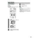
5
A
V MODE
Select a video setting: A
V
MODE (ST
ANDARD, DYNAMIC, MOVIE,
GAME, USER), PC MODE (ST
ANDARD, USER) (See page 51.)
6
SOUND
Select the sound multiplex mode.
7
(SRS and FOCUS)*
Select SRS and FOCUS sound system.
8
(Flashbac
k)
Pr
ess to r
etur
n to the pr
evious channel in nor
mal viewing mode.
Pr
ess to r
etur
n to the pr
evious page in TELETEXT mode.
9
/
(V
OLUME)
Set the volume.
10
(Re
veal hidden f
or
TELETEXT)
TELETEXT mode: Display hidden characters.
11
(SUBP
A
GE f
or
TELETEXT)
TELETEXT mode: Change the pictur
e mode for sub-page selecting.
12
MENU
Display the MENU scr
een.
13
(CHANNEL INFORMA
TION)
Display the channel infor
mation and time.
14
(INPUT SOURCE)
Select an input sour
ce. (TV
, INPUT 1, INPUT 2, INPUT 3, INPUT 4,
PC)
15
SLEEP
Set the Sleep timer
.
16
(MUTE)
Mute the sound.
17
0 – 9
TV/Exter
nal input mode: Set the channel.
TELETEXT mode: Set the page.
18
(Digit f
or c
hannel select)
Change the digits of the selected TV channel.
19
Colour (RED/GREEN/YELLO
W/BLUE)
TELETEXT mode: Select a page.
20
CH
/
CH
(
/
)
TV/Exter
nal input mode: Select the channel.
TELETEXT mode: Set the page.
21
(T
OP Overvie
w f
or
TELETEXT)
TELETEXT mode: Display an index page for CEEF
AX/FLOF
infor
mation. TOP Overview for TOP pr
ogramme.
22
(TELETEXT)
Select the TELETEXT mode. (all TV image, all TEXT image, TV/TEXT
image)
23
RETURN
MENU mode: Retur
n to the pr
evious menu scr
een.
24
ENTER
Execute a command.
Retur
n to the initial image position after moving with
/
/
/
.
25
/
/
/
(Cur
sor)
Select a desir
ed item on the setting scr
een.
Move the pictur
e on the scr
een.
1
2
3
4
5
6
7
8
9
10
11
12
14
15
13
16
17
18
19
20
21
22
23
24
25
NO
TE
•
When using the r
emote contr
ol unit, point it
at the Display
.
*
is a trademark of SRS Labs, Inc.
FOCUS technology is incorporated under
license fr
om SRS Labs, Inc.
Remote contr
ol unit
AC INPUT
110V–240V
DISPLAY INPUT2
DISPLAY INPUT1
System cable
A
VC System (rear vie
w)
AC cor
d
Displa
y
(rear vie
w
)
AC cor
d
System cable
(GREY)
Connect the plug fir
mly
until the hooks on both
sides click.
(WHITE)
Connect the plug into the
ter
minal and secur
e it by
tightening the thumb scr
ews.
(GREY)
(WHITE)
Setting the System
After putting the Display and the A
VC System in place, connect the system cables and AC cor
ds. Use the
cable clamp for bundling the cables.
Press do
wn the tw
o
upper hooks to remo
ve
the co
ver to
war
d y
ou.
Connecting the system cab
le and the A
C
cor
d to the Displa
y
1
2
3
Remo
ving the terminal co
ver
Connecting the system cab
le and the A
C
cor
d to the A
VC System
CA
UTION
•
T
O
PREVENT RISK OF ELECTRIC SHOCK,
DO NO
T
T
OUCH UN-INSULA
TED P
A
R
TS OF ANY CABLES
WITH
THE
A
C
CORD CONNECTED
.
6
LC-30HV4E
Preparation
4
5
6
Attaching the c
lamp to the leg of the Displa
y
Bundling the cables with the c
lamp
Closing the terminal co
ver
Displa
y (rear vie
w)
Cables come out fr
om
the small opening.
Setting the Displa
y on the wall
Setting the A
VC System with the stand
CA
UTION
•
Installing the LCD Colour TV r
equir
es special skill that should only be per
for
med by qualified service personnel.
Customers should not attempt to do the work themselves. SHARP bears no r
esponsibility for impr
oper mounting or
mounting that r
esults in accident or injur
y.
1
Using an optional brac
ket to mount the Displa
y
•
Y
ou can ask a qualified service personnel about using an optional AN-37AG1 bracket to mount the Display
to the wall.
•
Car
efully r
ead the instructions that come with the bracket befor
e beginning work.
V
e
rtical mounting
A
ngular mounting
Hanging on the wall
AN-37AG1 wall mount bracket. (See the bracket instructions for details.)
Ho
w to install the A
VC System ver
ticall
y using the stand unit.
•
Use the supplied stand unit for installing the A
VC System ver
tically in an upright position.
Stic
k eac
h spacer to the
stand as sho
wn.
Peel each spacer
away fr
om the
paper and attach
to the four bulging
ar
eas on the stand.
2
Attac
h each cushion to
the stand as sho
wn.
3
Fit the stand to the
AV
C
System.
Peel each cushion
away fr
om the
paper and attach
to the four ar
eas at
the bottom.
Inser
t the stand into the
AV
C
System, making sur
e that the
thick and thin bulges of the
stand align with the big and
small holes on the
AV
C
System.
Stand
spacer
Bulge
Stand cushion
Thin bulge
Thick
bulge
Big hole
Small
hole
4
Attach the stand using the
stand scre
ws as sho
wn.
Stand scr
ew
The A
V
C System installed
ver
ticall
y with the stand.
NO
TE
•
When mounting the A
VC System ver
tically
, always use the supplied stand. Be car
eful not to block vent holes when
standing up dir
ectly on the floor or a flat sur
face as this can r
esult in equipment failur
e.
Attaching point
Attaching point
Bulge
7
LC-30HV4E
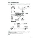
Using e
xternal equipment
Displa
y
(rear vie
w)
D
VD pla
y
e
r
A
VC System
(rear vie
w)
A
VC System
(fr
ont vie
w)
A
V
Receiver
(Built-in T
uner
Amp)
VCR
Decoder
Game console/Camcor
der
PC
Y
ou can connect many types of exter
nal equipment to your System, like a decoder
, VCR, DVD player
, PC, game
console and camcor
der
. T
o
view exter
nal sour
ce images, select the input sour
ce fr
om
b
on the r
e
mote
contr
ol unit or
INPUT
on the Display
.
CA
UTION
•
To
pr
otect all equipment, always turn
of
f the A
VC System befor
e connecting to a decoder
, VCR, DVD player
, PC, game
console, camcor
der or other exter
nal equipment.
•
The S-video signal only outputs when
“INPUT2
” or
“INPUT3
” is selected for
“Y/C
”, or when fr
om the INPUT 4 terminal
(S-
VIDEO). Only the S-video signal can output fr
om the INPUT 4 ter
minal (S-VIDEO).
NO
TE
•
Please r
e
fer to the r
e
levant operation manual (DVD player
, PC, etc.) car
efully befor
e making connections.
Remo
ving the speaker
s
This unit has detac
hable type speaker
s.
Y
ou can detach the system speakers when using exter
nal amplifier/speakers.
Befor
e detaching (or attaching) speakers, unplug the AC cor
d fr
om the AC outlet.
Bef
ore attaching/detac
hing speaker
s
•
Befor
e per
for
ming work make sur
e to tur
n of
f the System.
•
Befor
e per
for
ming work spr
ead cushioning over a flat sur
face to lay the Display on. This will pr
event it fr
om
being damaged.
CA
UTION
•
The speaker ter
m
inals on the Display is only for the attached speakers. Do not connect any thir
d par
ty plug or speaker to
the ter
m
inal.
•
Inser
t the speaker plug completely into the ter
minal.
•
Do not handle or move the Display by the speakers.
NO
TE
•
Per
for
m
the same steps for both left and right speakers.
•
To
attach the speakers, per
for
m
the above steps in r
everse or
der
.
123
Unfasten the scr
ews used to
secur
e the speakers in place.
Take hold of the speaker and
slowly slide it sideways.
(The speaker plug is still
inser
ted, so make sur
e not to
pull the speaker too far
.)
Remove the speaker plug fr
om
the ter
minal on the Display
.
(Do not r
e
move the plug by
pulling the cor
d.)
Now the speaker can be
detached fr
om the Display
.
Speaker
plug


