Read Sharp LC-28HM2E (serv.man3) Service Manual online
49
LC-28HM2
AN-28SP2
6
5
4
3
2
1
A
B
C
D
E
F
G
H
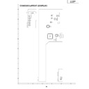
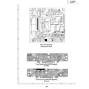
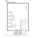
CHASSIS LAYOUT (DISPLAY)
50
LC-28HM2
AN-28SP2
6
5
4
3
2
1
A
B
C
D
E
F
G
H
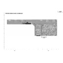
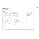
CHASSIS LAYOUT (AVC SYSTEM)
51
LC-28HM2
AN-28SP2
DESCRIPTION OF MAJOR IC FUNCTIONS
Ë
Display
»
IC4001 (IX3333CE)
Video signal decoder IC.
The decoded video signals are 8-bit digital RGB signals and supplied to the panel control G/A together with
the demodulated sync signals.
the demodulated sync signals.
»
IC4302 (IX3424CE)
Panel control G/A.
Based on the received video signals and the sync signals, it produces the timing signal for panel drive and
sends it to the panel together with the video signal. It also performs brightness frequency control and duty
ratio control for fluorescent lamp. Another function is the test pattern output. (Not used in normal operation)
sends it to the panel together with the video signal. It also performs brightness frequency control and duty
ratio control for fluorescent lamp. Another function is the test pattern output. (Not used in normal operation)
»
IC2004 (IX3421CE)
Monitor side microcomputer.
It performs various controls.
»
IC1101-1121, IC1124
Gradation power block.
Gradation power voltage generated by DAC is switched by using 1H reversing signal produced in IC4302
and is supplied to the panel switches
and is supplied to the panel switches
»
IC1304 (TA8184F)
Sound control IC.
Based on the DAC output voltage of user setting, it controls the headphone output volume, treble, bass,
balance and loudness.
balance and loudness.
Ë
AVC System
»
IC401 (CXA2069Q)
7-input and 3-output selector IC.
The video signals, except for PC and component signals, and all audio signals supplied from the terminal
board and the tuner will go into this IC for selection. Output 1 is used inside of the set, while output 3 is used
for monitor output. When S video data is outputted to monitor, Y and C signals are combined in this IC.
The video signals received in this IC next go to IC7001 (3-D Y/C separator IC).
Regarding audio signals, headphone output signal goes to IC301 (audio control IC) and speaker output
signal goes to the monitor via the buffer (IC308).
»
IC7001 (PD64082)
3-D Y/C separator IC.
All video signals or S video signals selected in IC401 pass through this IC, where 2-D or 3-D Y/C separation
is done after detecting the picture motion. Also, the edge emphasis is given to the picture. The detection of
EDTV signal, which is contained in the video signal, is also performed here.
The video signals received in this IC next to IC801 (video decoder IC).
is done after detecting the picture motion. Also, the edge emphasis is given to the picture. The detection of
EDTV signal, which is contained in the video signal, is also performed here.
The video signals received in this IC next to IC801 (video decoder IC).
»
IC801 (IX3113CE)
Video decoder IC.
Various adjustments are given to the video signals here, mainly in terms of contrast, tint, color, brightness
and a part of picture quality.
The received Y/C signal is once converted to the YUV signal in the 1st part of this IC. Analog switch selects
the converted signal and the component signal to feed them to the 2nd part of this IC, as well as to IC1901
(sync separator IC) and IC7201 (auto-wide IC). The video signal fed to the 2nd part of this IC is given the
various signal processing mentioned above and then converted to RGB signal for output. The outputted
video signal is sent to PC board after passing through different filters according to its frequency.
52
LC-28HM2
AN-28SP2
»
IC1901 (TA1300AN)
Sync separator IC.
When horizontal frequency is 15kHz (480i), IC801 can operate with its internal signal. When the frequency
is either 31kHz (480p) or 33kHz (1080i), the external clamp pulse needs to be supplied to IC IC801. This IC
produces such clamp pulse. The sync signal produced here, synchronized with the video signal, is supplied
to PC I/F PWB.
is either 31kHz (480p) or 33kHz (1080i), the external clamp pulse needs to be supplied to IC IC801. This IC
produces such clamp pulse. The sync signal produced here, synchronized with the video signal, is supplied
to PC I/F PWB.
»
IC7201 (IX3289CE)
Auto-wide IC.
This IC detects the scope of picture when the letterbox signal (the video signal showing black portion at top
and bottom of screen) with 15kHz horizontal frequency is received. It also detects presence of
superimposition, and is used for vertical position adjustment.
and bottom of screen) with 15kHz horizontal frequency is received. It also detects presence of
superimposition, and is used for vertical position adjustment.
»
IC3901 (CXA2020M)
Ground waves multiple sound IC.
The audio signal from the ground wave tuner (TU3201) is selected for output in accordance with user
setting suited for the audio mode. (Example: Main output in multiple sound mode, etc.)
setting suited for the audio mode. (Example: Main output in multiple sound mode, etc.)
»
IC301 (TA8184F)
Sound control IC.
Based on the DAC output voltage of user setting, it controls the headphone output volume, treble, bass,
balance and loudness.
balance and loudness.
»
IC415, IC416, IC417, IC403, IC404, IC405 (ADG704)
Wide bank 4:1 input analog selector IC.
One IC of IC415, IC416 or UC417 selects PC and component video signals. Then, among IC403, IC404
and C405, the choice is made whether the signal goes to PC board or goes to AV system video processing
at IC801, etc.
and C405, the choice is made whether the signal goes to PC board or goes to AV system video processing
at IC801, etc.
The video signals thus received at PC board will be digitized by AD converter, given size and positional
adjustments, synthesized in OSD, encoded to the serial data, and then sent out to the monitor.
adjustments, synthesized in OSD, encoded to the serial data, and then sent out to the monitor.
* Component signal
Y+ component video signal supplied from D terminal 1 and D terminal 2.

