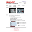
Read Sharp LC-26GA5E (serv.man31) Technical Bulletin online
LCD 2005 07 01
Date of Issue: 4
th
July 2005
Classification:
Yellow
LCD TELEVISION TECHNICAL BULLETIN
Page 1 of 1
Sharp Electronics (UK) Limited
Reference - MB 04 072005 - 1
Revision - 1
White – Carry out as required
Yellow – Carry out as required and whenever the unit comes in for service
Red – Carry out on all units
MODEL
LC26GA5E
LC32GA5E
LC37GA5E
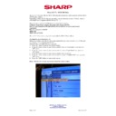
SYMPTOM Intermittently the unit will not switch on or the green LED is illuminated but there is no
picture (remote control functions do not work).
CAUSE
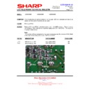
R713 and R721.
ACTION
Replace R713 and R721 (both 0
Ω
resistors) with 10
Ω
SMD resistors. These resistors
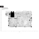
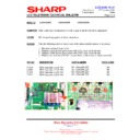
are located on the underside of the power supply near Q701 and Q702. This is part of
the power factor circuit.
the power factor circuit.
Note
The position of these components may vary depending upon the version of PWB fitted
to the unit, but will always be close to Q701 and Q702
The position of these components may vary depending upon the version of PWB fitted
to the unit, but will always be close to Q701 and Q702
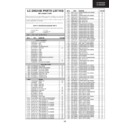
REF NO
DESCRIPTION
PART NUMBER
PRICE CODE
R713
SMD Resistor, 10
Ω
VRS-TS2AD100J
AA
R721
SMD Resistor, 10
Ω
VRS-TS2AD100J
AA
R713
R721
Display

