Read Sharp LC-26GA5E (serv.man18) Service Manual online
93
LC-26GA5E
LC-32GA5E
LC-32GA5E
LC-26GA5E
LC-32GA5E
LC-32GA5E
52
125
126
127
128
129
130
131
132
133
134
135
136
137
138
139
140
51
50
49
48
47
46
45
44
43
42
41
40
39
38
37
108107106105104103102101100 99 98 97 96 95 94 93
53
54
55
56
57
58
59
60
61
62
63
64
65
66
67
68
109
110
111
112
113
114
115
116
117
118
119
120
121
122
123
124
92 91 90 89 88 87 86 85 84 83 82 81 80 79 78 77 76 75 74 73
1
2
3
4
5
6
7
8
9 10 11 12 13 14 15 16 17 18 19 20 21 22 23 24 25 26 27 28 29 30 31 32 33 34 35 36
69
70
71
72
141
142
143
144
CLKIN2
UVIN0
UVIN1
UVIN2
UVIN3
VSSP8
VDDP8
VDD8M
VSSD60
VSSD61
VDDD60
VDDD61
UVIN4
UVIN5
UVIN6
UVIN7
VSSP7
VDDP7
TMS
NC
TDO/SVMOFF
TDI
TCLK
INTR
656I02
656I12
656I22
656I32
656I42
656I52
656I62
656I72
NC
656i0/YIN0
VSSP9
VDDP9
YOUT6
NC
VSSP3
VDDP3
VSSD2
VDDD2
YOUT7
YOUT8
YOUT9
RGBOUT0
RGBOUT1
RGBOUT2
RGBOUT3
RESET
VDDP2
VSSP2
YOUT5
VSSP4
YOUT4
VDDP4
YOUT3
YOUT2
YOUT1
YOUT0
CLKF20
UVOUT9
VSSD30
VSSD31
VDDD30
VDDD31
UVOUT8
UVOUT7
VSSP50
VSSP51
VSSP52
VDDP5
NC
SDA
SCL
NC
NC
VDDD5
VSSD5
VDDA4
VSSA4
NC
VSSA3
AVOUT
VDDA3
VSSA2
AYOUT
VDDA2
VSSA1
AUOUT
NC
NC
UVOUT5
NC
UVOUT4/INTR
VDDP6
VSSP6
UVOUT3
UVOUT2
UVOUT6
UVOUT1
UVOUT0
VDDD4
VSSD4
VDDA0
ASVMOUT
VSSA0
VDDA1
TEST
656i1/YIN1
656i2/YIN2
VIN
656i3/YIN3
656i4/YIN4
VDDP0
VSSP0
HIN
NC
656i5/YIN5
656i6/YIN6
656i7/YIN7
CLKIN
VDDD0
VSSD0
AVI
VDDAPLL
HOUT
VOUT
AVO/ITR
RGBOUT4
RGBOUT5
RGBOUT6
RGBOUT7
RGBOUT8
RGBOUT9
CLKOUT
VDDP1
VSSP1
XOUT
XIN
VDDD11
VDDD10
VSSD1
VSSAPLL
FRC 9428A
FRC 9429A
FRC 9429A
FRC 9419A
FAMOUS
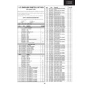
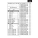
MAJOR ICs INFORMATION
1. IC1001 (RH-IXB058WJZZ)
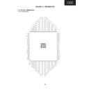
1.1. Pin Configuration
94
LC-26GA5E
LC-32GA5E
LC-32GA5E
LC-26GA5E
LC-32GA5E
LC-32GA5E
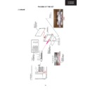
1.2. Block Diagram
Divider
ITU656/ITU601
Decoder
648 MHz
clock
Free-running Clocks
Global
Motion-,
Still-,
Stock-
Detection
648 MHz
DTO
Xtal
Oscillator
24
23
XOUT
XIN
Divider
Line-locked Clocks
LL-PLL
ISM
17
AVI
Input Processing
Clock Sync Generation
105
106
114
111
115
113
TDI
SCL
SDA
Test-controller,
Memory bist
TCLK TMS
TDO
RESET
Chip Control
Control
67
68
73
76
78
81
82
83
97
91
94
8:8:8
ITU656
ITU601
ITU601
Encoder
AVOUT
AUOUT
AYOUT
Pixel-
mixer
mixer
YOUT7
YOUT6
YOUT5
YOUT4
YOUT3
YOUT2
YOUT1
YOUT0
52
53
55
57
58
59
UVOUT2
UVOUT3
UVOUT4/INTR
UVOUT5
UVOUT6
UVOUT7
Display Processing
Delay Adjust
88
ASVMOUT
126
127
128
129
137
138
139
140
UVIN0
UVIN1
UVIN2
UVIN3
UVIN4
UVIN5
UVIN6
UVIN7
142
3
4
6
7
11
12
13
656I0/
YIN0
656I1/
YIN1
656I2/
YIN2
656I3/
YIN3
656I4/
YIN4
656I5/
YIN5
656I6/
YIN6
656I7/
YIN7
5
CLKIN
14
10
HIN
VIN
HDTV
Bypass
eDRAM
Memory
Controller
data b
uff
er
data b
uff
er
4:2:2
Output
Sync
Controller
FRC 9419A
FRC 9428A
FRC 9429A
FRC 9428A
FRC 9429A
FAMOUS
Output Processing
HOUT
VOUT
CLKOUT
36
34
35
33
AVO/INTR
Filmmode
Detection
ISS
Noise
Reduction
Local Motion
Detection
8:4:4
8:8:8
8:8:8
MUX
DCE
Contrast
LSE
CTE
CTE
Brightness
Curtain
Generator
Pattern
Generator
Frame
Generator
I
2
C
Interface
C800
Controller
SVM DAC
Y DAC
U DAC
V DAC
GAIN
GAIN
GAIN
GAIN
NCE
Bit
Reduction
Matrix
Saturation
Tint
SVM
H-panorama
Generator
V-panorama
Generator
H-postscaler
V-postscaler
2D LSE
MEX
Motion
Tracking
Vector
Memory
Block
Line
Converter
Frame
Rate
Interpolation
Line
Block
Converter
Output
Data
Controller
to pin 33/78
117
118
119
120
121
122
123
124
125
656I02
62
YOUT8
YOUT9
84
60
UVOUT0
46
45
UVOUT1
UVOUT8
44
UVOUT9
30
31
32
40
41
42
43
RGBOUT0
29
28
27
RGBOUT1
RGBOUT2
RGBOUT3
RGBOUT4
RGBOUT5
RGBOUT6
RGBOUT7
RGBOUT8
RGBOUT9
61
CLKF20
116
INTR
656I12
656I22
656I32
656I42
656I52
656I62
656I72
CLKIN2
H-/V-
Prescaler
39
95
LC-26GA5E
LC-32GA5E
LC-32GA5E
LC-26GA5E
LC-32GA5E
LC-32GA5E
NC = not connected, leave vacant
LV = not used, leave vacant
LV = not used, leave vacant
Pin No.
Pin Name
Type
Connection
(If not used)
Short Description
PMQFP144-4
1
NC
NC
2
LV
Test, do not use
3
656I1/YIN1
I
LV (pull
down)
down)
Digital (luminance) input
4
656I2/YIN2
I
LV (pull
down)
down)
Digital (luminance) input
5
VIN
I
LV (pull
down)
down)
Vertical sync input
6
656I3/YIN3
I
LV (pull
down)
down)
Digital (luminance) input
7
656I4/YIN4
I
LV (pull
down)
down)
Digital (luminance) input
8
VDDP0
S
Supply digital pad (3.3 V)
9
VSSP0
S
Supply digital pad (0 V)
10
HIN
I
LV (pull
down)
down)
Horizontal sync input
11
656I5/YIN5
I
LV (pull
down)
down)
Digital (luminance) input
12
656I6/YIN6
I
LV (pull
down)
down)
Digital (luminance) input
13
656I7/YIN7
I
LV (pull
down)
down)
Digital (luminance) input [MSB]
14
CLKIN
I
Clock input (max. 81.0 MHz)
15
VDDD0
S
Supply digital pad (1.8 V)
16
VSSD0
S
Supply digital pad (0 V)
17
AVI
I
LV (pull
down)
down)
Active video input
18
VDDAPLL
S
Supply analog PLL (1.8 V)
19
VSSAPLL
S
Supply analog PLL (0 V)
20
VSSD1
S
Supply digital core (0 V)
21
VDDD10
S
Supply digital core (1.8 V)
22
VDDD11
S
Supply digital core (1.8 V)
23
XIN
I
Crystal connection 1
1.3. Description of Pins IC1001
96
LC-26GA5E
LC-32GA5E
LC-32GA5E
LC-26GA5E
LC-32GA5E
LC-32GA5E
24
XOUT
O
LV (pull
down)
down)
Crystal connection 2
25
VSSP1
S
Supply digital pad (0 V)
26
VDDP1
S
Suplly digital pad (3.3 V)
27
RGBOUT9
O
LV
Tristate (SELOMODE=0)
Digital (red: SELRB=0; blue: SELRB=1;)
Output [MSB](SELOMODE=1)
Output [MSB](SELOMODE=1)
28
RGBOUT8
O
LV
Tristate (SELOMODE=0)
Digital (red: SELRB=0; blue: SELRB=1;)
Output (SELOMODE=1)
Output (SELOMODE=1)
29
RGBOUT7
O
LV
Tristate (SELOMODE=0)
Digital (red: SELRB=0; blue: SELRB=1;)
Output (SELOMODE=1)
Output (SELOMODE=1)
30
RGBOUT6
O
LV
Tristate (SELOMODE=0)
Digital (red: SELRB=0; blue: SELRB=1;)
Output (SELOMODE=1)
Output (SELOMODE=1)
31
RGBOUT5
O
LV
Tristate (SELOMODE=0)
Digital (red: SELRB=0; blue: SELRB=1;)
output (SELOMODE=1)
output (SELOMODE=1)
32
RGBOUT4
O
LV
Tristate (SELOMODE=0)
Digital (red: SELRB=0; blue: SELRB=1;)
Output (SELOMODE=1)
Output (SELOMODE=1)
33
AVO/ITR
O
LV
Active video output (CPUIRQ=0)
Interrupt signal output from µC (CPUIRQ=1)
Static 0 (CPUIRQ=2)
Static 1 (CPUIRQ=3)
Interrupt signal output from µC (CPUIRQ=1)
Static 0 (CPUIRQ=2)
Static 1 (CPUIRQ=3)
34
VOUT
O
LV
Vertical sync output
35
HOUT
O
LV
Horizontal sync output.
(Synchronized to 40.5-81 MHz CLKOUTSEL72=1)
(Synchronized to 20.25-40.5 MHz
CLKOUTSEL72=0 and CLKOUTSEL=1)
(Synchronized to 15.1875-30.75 MHz
CLKOUTSEL72=0 and CLKOUTSEL=0)
(Synchronized to 20.25-40.5 MHz
CLKOUTSEL72=0 and CLKOUTSEL=1)
(Synchronized to 15.1875-30.75 MHz
CLKOUTSEL72=0 and CLKOUTSEL=0)
36
CLKOUT
O
LV
Output clock disabled (CLKOUTON=0)
Output clock (max. 81 MHz) (CLKOUT=1)
Output clock (max. 81 MHz) (CLKOUT=1)
(40.5-81 MHz CLKOUT72=1
20.25-40.5 MHz CLKOUT72=0 and CLKOUTSEL=1
1515.1875-30.37 MHz CLKOUT72=0 and
CLKOUTSEL=0)
20.25-40.5 MHz CLKOUT72=0 and CLKOUTSEL=1
1515.1875-30.37 MHz CLKOUT72=0 and
CLKOUTSEL=0)
37
VSSP2
S
Supply digital pad (0 V)
38
VDDP2
S
Supply digital pad (3.3 V)
Pin No.
Pin Name
Type
Connection
(If not used)
Short Description
PMQFP144-4
1.3. Description of Pins IC1001, continued

