Read Sharp LC-26GA3 (serv.man8) Service Manual online
34
LC-26GA3E
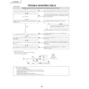
TROUBLE SHOOTING TABLE
YES
YES
YES
NO
YES
NO
YES
YES
NO
NO
NO
NO
NO
<Power supply>
No power supply (Front LED is off) or no power-up (Front LED does not change from red to green)
Is the power supply cord properly connected to the main unit?
Is BU+5V line (pin (16) of CN706, pin(8) of CN707 and pin (5) of
CN708) normal?
CN708) normal?
Is there any defective part or short-circuit in BU+5V line?
Check the 15V line power circuits (T701, T702, F704, Q706-714,
PC703-704, D708-717, IC702, L710, Q733-736, D735-736, D780
and IC706).
PC703-704, D708-717, IC702, L710, Q733-736, D735-736, D780
and IC706).
Check each DC/DC converter and line (IC707-711 and IC716).
Replace if necessary.
Replace if necessary.
Is a voltage (approx. 380 V) available at C709/C710 when power
is turned on?
is turned on?
Is the voltage available in 15 V line immediately after the power is
turned on?
turned on?
Is each DC/DC converter output (IC707-711 and IC716) normal?
Reconnect the wire harness, FFC, etc. in the set properly, and
repeat the check.
repeat the check.
Check the 380V line power circuit (L703, IC701, Q701 - 5, D706
and TH701).
and TH701).
Connect the power supply cord properly, and turn on the power.
Is F701 normal?
Replace F701and F702, and then turn on the power. If the fuse still
blown, replace VA702, D701, D702, L703, Q701, Q702 and IC701.
Then repeat the check.
blown, replace VA702, D701, D702, L703, Q701, Q702 and IC701.
Then repeat the check.
Check the BU+5V line power circuit (F703, D722,
IC703, T703, PC702, D761 and D784.
IC703, T703, PC702, D761 and D784.
Remove the defective part or short-circuit, and repeat the check.
Are the wire harness, FFC, etc. in the set connected properly?
•
Power switch: Top panel
(Main) Power (DC cutoff: Detected by microprocessor)
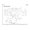
[Scheme of power supply system]
[(Main) Power OFF sequence]
1) (Main) Power OFF (DC switch)
2) (Main) Power shutoff is detected by the monitor microprocessor port.
3) Standby request (power cord) is sent to Seine from the microprocessor.
4) Seine shutdown process
5) Reception of shutdown permission from Seine
6) Monitor microcomputer turns off the relay to enter the standby mode.
YES
YES
Monitor microprocessor
Backup
Relay
Seine
(Main) Power
Main
PS-ON
35
LC-26GA3E
TROUBLE SHOOTING TABLE
(Continued)
NO
NO
NO
NO
NO
NO
YES
YES
YES
YES
YES
YES
YES
YES
YES
YES
YES
No sound comes out.
(1)
No sound comes out at UHF/VHF reception.
Is the SIF output from the tuner as
specified?(TU1
101_Pin7)
Are the audio outputs (A-OUT_L/R) from pins (28)
and (29) of IC2714 as specified?
Are the audio outputs from pins (28) and (29) of
IC2714 to pins (13) and (15) of P3801 (1-bit
amplifier input) as specified?
Is the signal from the 1-bit amplifier inputted to
each terminal of P3810?
Is relay normally switched from R
Y3801 (speaker
switching) of
A
V
PWB ?
Are the audio signals from pins (34) and (33)
(SC2_OUTL/R) of IC2701 to pins (32) and (33) of
IC2714 (DIR) as specified?
Is the input signal to pin (67) (ANA_IN1+) and pin
(69) (ANA_IN2) of IC2701
(MUL
TI_SOUND_PROCESSOR) as specified?
Check
TU1
101 (UV tuner) and its peripheral
circuits.
No external input sound comes out.
Are the audio signals inputted to pins (56) (L-ch) and (57) (R-ch) of IC2701?
Is the L-ch audio signal outputted to pin (52) of IC3801?
Is the R-ch audio signal outputted to pin (54) of IC3801?
<INPUT
-1>
Is the L-ch audio signal inputted from pin (6) of input terminal SC1
101 to pin (2) of IC3801?
Is the R-ch audio signal inputted from pin (2) of input terminal SC1
101 to pin (4) of IC3801?
<INPUT
-2>
Is the L-ch audio signal inputted from pin (6) of input terminal SC1
102 to pin (9) of IC3801?
Is the R-ch audio signal inputted from pin (2) of input terminal SC1
102 to pin (1
1) of IC3801?
<INPUT
-3>
Is the L-ch audio signal inputted from pin (2) of input terminal J1
101 to pin (16) of IC3801?
Is the R-ch audio signal inputted from pin (5) of input terminal J1
101 to pin (18) of IC3801?
<INPUT
-4>
Is the L-ch audio signal inputted from pin (2) of input terminal J1900 to pin (29) of IC3801?
Is the R-ch audio signal inputted from pin (3) of input terminal J1900 to pin (31) of IC3801?
Check the peripheral circuits of filter circuits
(Q1
121-2) (Q1
1
19-20).
Check IC2714 and its peripheral circuits.
Check the 1-bit amplifier and its peripheral circuits.
Check the lines from pins (28) and (29) of IC2714
to pins (13) and (15) of P3801 (1-bit amplifier
input).(IC3802, Q3805-6)
Are signals LRCK, BICK, SDT
O and SDT
O
inputted/outputted from IC2714 to IC2710 (DSP)
normally?
Check the lines from pins (34) and (33)
(SC2_OUTL/R) of IC2701 to pins (32) and (33) of
IC2714.
YES
YES
YES
NO
NO
No sound comes out from the headphones.
Check IC2714 and its peripheral circuits.
Check the mute control terminal pin (2) of
IC2702.H:
Active, L: Mute
Are audio output pins (26) and (27) of IC2714
(DIR) as specified?
Are audio output pins (1) and (7) of IC2702
(H/P_AMP) as specified?
Check J2402 (HEAD_PHON_JACK) and its
peripheral circuits.
NO
NO
NO
YES
YES
YES
YES
YES
No sound comes out.
(2)
No sound comes out.
(3)
Are audio output pins (37) and (36)
(SC1_OUT_L/R) of IC2701 (MUL
TI_SOUND_
PROCESSOR) as specified?
Are audio output pins (7) and (1) of IC2704
(EQ_AMP) as specified?
Is MUTE circuit normal? (Q1
1
16-7)
Check
AUDIO OUTPUT
terminal peripheral circuit.
No monitor audio output comes out.
Is the monitor audio output set to anything other
than "V
ariable"?
Are the headphones disconnected?
Check IC2701 and its peripheral circuits.
Check IC2704 and its peripheral circuits.
Check Q1
1
16-7 and M.MUTE line.
36
LC-26GA3E
TROUBLE SHOOTING TABLE
(Continued)
YES
YES
YES
YES
YES
NO
NO
YES
YES
NO
NO
YES
YES
NO
NO
NO
NO
NO
NO
YES
YES
NO
NO
YES
YES
NO
NO
YES
YES
YES
NO
NO
YES
YES
<LC-26GA3/4E>
No video output (1)
<CVBS,
Y/C, S-video signal> input
External input image does not appear
.
(INPUT
-1)
Is INPUT
-1 selected on the input switching
menu screen?
Select INPUT
-1 on the input
switching menu screen and
then select the input signal.
<CVBS signal input>
Check between pin (20) of
SC1
101 and pin (1) of IC3801.
Is signal supplied to each input terminal of
IC3801 (A
V SWITCH)?
<CVBS signal input>
Is image signal supplied to pin (1)?
Is INPUT
-2 selected on the input switching
menu screen?
Select INPUT
-2 on the input
switching menu screen and
then select the input signal.
<CVBS signal input>
Check between pin (20) of
SC1
102 and pin (8) of IC3801.
<Y/C signal input>
Check between pin (20,15) of
SC1
102 and pin (10,12) of
IC3801.
Is signal supplied to each input terminal of
IC3801 (A
V SWITCH)?
<CVBS signal input>
Is image signal supplied to pin (8)?
<Y/C video signal input>
Are
Y
and C supplied to pins (10) and (12).
Check IC3801 (A
V SWITCH) and the
peripheral circuits.
Is digital image signal sent from pins (124)-
(133) and (140)-(159) of IC402?
Are there digital video signal inputs at pins (53), (54), (57)~(60), (51), (52) (RE0-7), pins(63)~(68), (61), (62) (GE0-7), pin
s (73)~(78), (69), (70)
(BE0-7), pins (81)~(86), (79), (80) (RO0-7), pins (91)~(96), (89), (90) (GO0-7), pins (99), (100), (1), (2), (5), (6), (97), (9
8) (BO0-7), and pins
(7)~(10) (HSYNC, VSYNC, DE, CLKIN) of IC3201 (L
VDS
TRANSMITTER)?
Are there digital video signal outputs at pins (49)(T
A1—), (48)(T
A1+), (47)(TB1—), (46)(TB1+), (44)(TC1—), (43)(TC1+),(41)(TCLK
—),
(42)(TCLK+), (40)(TD1—), (39)(TD1+), (37)(T
A2—), (36)(T
A2+), (35)(TB2—), (34)(TB2+), (32)(TC2—), (31)(TC2+), (30)(TCLK2—),(29)(
TCLK2+),
(28)(TD2—), and (27)(TD2+) of IC3201?
<CVBS, VIDEO signal input>
Are MAIN image signal and SUB image signal supplied to pins (56) and (44) of IC3801, respectively?
<Y/C, S-VIDEO signal input>
Are MAIN-Y
signal, MAIN-C signal, SUB-Y
signal and SUB-C signal supplied to pins (56),(58),(44) and
(47) of IC3801, respectively?
<CVBS, VIDEO signal input> Is image signal supplied to pin 8 of IC401 (MAIN L.P
.F
.) and pin (2) of IC600 (SUB L.P
.F
.)?
<Y/C, S-VIDEO signal input>
Are MAIN-Y
signal, MAIN-C signal, SUB-Y
signal and SUB-C signal supplied to pins (8) and (1
1) of IC
401 and pins (2) and (6) of
IC600, respectively?
External input image does not appear
.
(INPUT
-2)
Is INPUT
-3 selected on the input switching
menu screen?
Select INPUT
-3 on the input
switching menu screen and
then select the input signal.
<VIDEO signal input>
Check between pin (8) of J1
101
and pin (15) of IC3801.
<S-video signal input>
Check between pin (3,4) of
SC1
103 and pin (17,19) of
IC3801.
Is signal supplied to each input terminal of
IC3801 (A
V SWITCH)?
<VIDEO signal input>
Is image signal supplied to pin (15)?
<S-video signal input>
Are
Y
and C supplied to pins (17) and (19).
External input image does not appear
.
(INPUT
-3)
Check between IC3801 and IC401/IC600.
<CVBS, VIDEO signal input>
Is image signal supplied to pin (8) of IC402
(MAIN 3D-YC & CHROMA)?
<Y/C, S-VIDEO signal input>
Are
Y
and C supplied to pins (8) and (18) of
IC402 (MAIN 3D-YC & CHROMA),
<MAIN VIDEO>
3D-YC<P
AL>
Check between IC401 and IC402.
Check IC 402 and the peripheral
circuits.
Is digital image signal sent from pins (1
15)-
(126) and (133)-(144) of IC502?
<CVBS, VIDEO signal input>
Is image signal supplied to pin (12) of IC502
(MAIN 2D-YC & CHROMA)?
<Y/C, S-VIDEO signal input>
Are
Y
and C supplied to pins (12) and (16) of
IC502 (MAIN 2D-YC & CHROMA),
<MAIN VIDEO>
2D-YC<SECAM>
Check between IC401 and IC502.
Check IC 502 and the peripheral
circuits.
Is digital image signal sent from pins (31)-
(40) and (41)-(50) of IC601?
<CVBS, VIDEO signal input>
Is image signal supplied to pin (72) of IC601
(SUB 2D-YC & CHROMA)?
<Y/C, S-VIDEO signal input>
Are
Y
and C supplied to pins (72) and (71) of
IC601 (SUB 2D-YC & CHROMA),
<SUB VIDEO>
Check between IC401 and IC601.
Check IC 601 and the peripheral
circuits.
Replace the main PWB, or check between
IC402/IC502/601 and IC3201.
Check IC3201 (L
VDS
TRANSMITTER) and
the peripheral circuits.
Check the LCD CONTROLLER PWB.
37
LC-26GA3E
TROUBLE SHOOTING TABLE
(Continued)
YES
YES
YES
YES
YES
YES
NO
NO
NO
External input in trouble <INPUT
-1>
Is INPUT
-1 selected in the input switching
menu screen?
Is there signal input at each input pin of
IC3805 (A
V SWITCH)?
<RGB signal input>
Is RGB signal supplied to pins (63), (61)
and (59)?
<COMPONENT
/ RGB signal> input
Are MAIN image signal, P
ASS image signal and SUB image signal sent to pins (50), (48) and (46) (Y
Pb, Pr), pins (38), (36) and
(34) (Y
Pb, Pr) and pins (44),
(42) and (40) (Y
Pb, Pr) of IC3805, respectively?
No video output (2)
Check IC3805 (A
V SWITCH) and the
peripheral circuits.
Are there digital video signal inputs at pins (53), (54), (57)~(60), (51), (52) (RE0-7), pins(63)~(68), (61), (62) (GE0-7), pin
s (73)~(78), (69), (70) (BE0-7), pins
(81)~(86), (79), (80) (RO0-7), pins (91)~(96), (89), (90) (GO0-7), pins (99), (100), (1), (2), (5), (6), (97), (98) (BO0-7), an
d pins (7)~(10) (HSYNC, VSYNC, DE,
CLKIN) of IC3201 (L
VDS
TRANSMITTER)?
Are there digital video signal outputs at pins (49)(T
A1—), (48)(T
A1+), (47)(TB1—), (46)(TB1+), (44)(TC1—), (43)(TC1+), (41)(TCL
K—), (42)(TCLK+), (40)(TD1—),
(39)(TD1+), (37)(T
A2—), (36)(T
A2+), (35)(TB2—), (34)(TB2+), (32)(TC2—), (31)(TC2+), (30)(TCLK2—),(29)(TCLK2+), (28)(TD2—), and
(27)(TD2+) of IC3201?
Replace the main PWB, or check between
IC402/IC502/IC601 and IC3201.
Check IC3201 (L
VDS
TRANSMITTER) and
the peripheral circuits.
Check the LCD CONTROLLER PWB.
NO
Select INPUT
-1 on the input
switching menu screen and
then select the input signal.
NO
<RGB signal input>
Check between pins (15), (1
1)
and (7) of SC1
101 and pins
(63), (61) and (59) of IC3805.
External input in trouble <INPUT
-3>
Is INPUT
-3 selected in the input switching
menu screen?
Is there signal input at each input pin of
IC3805 (A
V SWITCH)?
<COMPONENT
signal input>
Is
Y
, Pb, Pr signal supplied to pins (15), (17)
and (19)?
NO
Select INPUT
-3 on the input
switching menu screen and
then select the input signal.
NO
<COMPONENT
signal input>
Check between pins (9), (6)
and (3) of J1
101 and pins (15),
(17) and (19) of IC3801.
YES
YES
YES
NO
NO
YES
Is digital image signal sent from pins (1
15)-
(126) and (133)-(144) of IC502?
Is MAIN image signal supplied from pins
(50), (48) and (46) (Y
Pb, Pr) of IC3805 to
pins (24), (29) and (32) (Y
Cb, Cr) of IC502
(2D-YC & CHROMA)?
<RGB signal>
<MAIN >
Check between IC3805 and IC502.
YES
NO
YES
Is video signal supplied from pins (44), (42)
and (40) (Y
Pb, Pr) of IC3805 to pins (8),
(10) and (13) (Y
Pb, Pr) of IC600 (L.P
.F)?
Is video signal supplied from pins (2), (1) and
(3) (Y
Cb, Cr) of IC601 (2D-YC & CHROMA)?
<RGB/COMPONENT
signal>
<SUB>
Check between IC3805 and IC600.
YES
NO
Is digital image signal sent from pins (31)-
(40) and (41)-(50) of IC601?
Check between IC600 and IC601.
Check IC 502 and the peripheral
circuits.
NO
Check IC 601 and the peripheral
circuits.
YES
NO
YES
Is video signal supplied from pins (38), (36)
and (34) (Y
Pb, Pr) of IC3805 to pins (9),
(12) and (14) (Y
Pb, Pr) of IC401 (L.P
.F)?
Is MAIN image signal supplied from pins (8),
(18) and (20) (Y
Cb, Cr) of IC402 (3D-YC &
CHROMA)?
<COMPONENT
signal>
<MAIN>
Check between IC3805 and IC401.
YES
YES
NO
Is digital image signal sent from pins (124)-
(133) and (140)-(159) of IC402?
Check between IC401 and IC402.
NO
Check IC 402 and the peripheral
circuits.

