Read Sharp LC-26GA3 (serv.man6) Service Manual online
13
LC-26GA3E
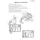
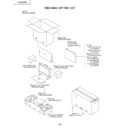
REMOVING OF MAJOR PARTS
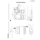
1. Remove the Terminal Covers 1 .
2. Remove the 4 lock screws 2 and detach the Stand.
3. Remove the 4 lock screws 3 and detach the bracket cover.
4. Remove the 4 lock screws 4 and separate the Speaker Box from the set.
Disconnect the SP Wire (R) and SP Wire (L).
5. Remove the 15 lock screws 5 from the Rear Cabinet, and detach the Rear Cabinet.
6. Remove the 4 lock screws 6 from the Center Angle, and detach the Center Angle.
7. Remove the Key PWB.
7-1. Remove the 2 lock screws 7 from the Top Cover.
7-2. Remove the 2 lock screws 8 from the Key PWB.
8. Remove the 1 lock screw 9 from the Frame Cover, and detach the Frame Cover.
9. Disconnect all the connectors from all the PWBs.
1
1
2
3
3
4
4
5
5
5
Terminal Cover(R)
Bracket Cover
SP Bracket
SP Wire(R)
SP Wire(L)
SP Bracket
Terminal
Cover (B)
Cover (B)
Bracket Cover
Terminal Cover(L)
Stand
Speaker Box
Rear Cabinet
Front Cabinet
P2002
SC3802
P8506
P1901
P7200
SC7200
P7706
P3101
SC3200
SC4601
P151
Center Angle
Top Cover
Key PWB
Frame Cover
6
7
8
9
P2006
P7201
P1902
P1501
P3805
P3700
P3802
P1900
14
LC-26GA3E
10. Remove the Main and CPU PWBs.
10-1. Remove the 8 lock screws 10 from the Main PWB shield, and detach the Main PWB shield.
10-2. Remove the 14 lock screws 11 from the Main Top Shield, and detach the Main Top Shield.
10-3. Remove the 3 lock screws 12 from the BS terminal cover, and detach the BS terminal cover.
11. Detach the DVI PWB.
11-1. Remove the 8 lock screws 13 from DVI PWB.
11-2. Remove the 4 lock screws 14 from the AV-Sub Angle, and detach the AV-Sub Angle.
12. Remove the 3 lock screws 15 from the DC fan, and detach the DC fan.
13. Disconnect all the connectors from all the PWBs.
C707
P5703
CN706
CN708
P7708
P1804
P1803
P8502
13
13
14
10
10
10
12
12
15
14
Main PWB Shield
AV-Sub Angle
DVI PWB
BS Terminal Cover
Card Cover
DC Fan
CPU PWB
Main PWB
CN7602
CN7603
CN7604
CN7605
CN7606
CN7607
CN7608
CN7601
P202
P7704
SC4651
SC4652
P7705
P7707
CN704
CN705
CN7501
CN7502
CN7503
CN7504
CN7505
CN7506
CN7507
CN7508
P2004
P3811
P3801
P3808
P101
P6001
P3810
P3807
P2003
P2002
SC3802
P8506
P1901
P7200
SC7200
P7706
P3101
SC3200
SC4601
Main Top Shield
11
11
11
11
15
LC-26GA3E
14. Remove the 3 lock screws 16 from the AV PWB, and detach the AV PWB.
15. Remove the 1 lock screw 17 from the EXT.SP PWB, and detach the EXT.SP PWB.
16. Remove the 6 lock screws 18 from the AV PWB shield, and detach the AV PWB shield.
17. Remove the 6 lock screws 19 from the LCD controller PWB, and detach the LCD controller PWB.
18. Remove the 5 lock screws 20 from the Power PWB, and detach the Power PWB.
19. Remove the 3 lock screws 21 from the Inverter-GND PWB, and detach the Inverter-GND PWB.
20. Remove the 4 lock screws 22 from the Inverter PWB, and detach the Inverter PWB.
21. Remove the 2 lock screws 23 from the 1-bit AMP. PWB, and detach the 1-bit AMP. PWB.
22. Remove the 4 lock screws 24 form the speaker angle(right), and detach the speaker angle(right).
23. Remove the 4 lock screws 25 form the speaker angle(left), and detach the speaker angle(left).
24. Remove the 8 lock screws 26 form the fixing metals, and detach the fixing metals.
25. Remove the 2 lock screws 27 from the R/C, LED PWB, and detach the R/C, LED PWB.
26. Remove the 4 lock screws 28 from the fixing metal, and detach the fixing metal.
27. Remove the 2 lock screws 29 from the core angles, and detach the core angles.
28. Remove the 2 lock screws 30 from the LCD panel unit ass’y, and detach the LCD panel unit ass’y.
22
20
19
21
16
17
18
18
Inverter PWB
Power PWB
Inverter-GND PWB
AV PWB
EXT. SP PWB
AV PWB Shield
LCD Controller PWB
25
26
26
26
28
28
24
24
27
25
26
30
29
29
23
Fixing Metal
LCD Panel Unit Ass’y
Fixing Metal
Fixing Metal
SP Angle(L)
R/C, LED PWB
SP Angle(R)
1-bit AMP. PWB
Core Angle
16
LC-26GA3E
29. Remove the 4 lock screws 31 from the LCD Panel Unit, and detach the LCD Panel Unit.
30. Detach the sheet spacer-A/sheet spacer-B and sheet spacer-S.
31. Detach the Prism, Diffusion and Reflection/Deflection Sheets and Diffusion Panel.
32. Remove the 2 lock screws 32 from the Lamp Holder Ass'y(top), and detach the Lamp Holer Ass'y(top).
30. Detach the sheet spacer-A/sheet spacer-B and sheet spacer-S.
31. Detach the Prism, Diffusion and Reflection/Deflection Sheets and Diffusion Panel.
32. Remove the 2 lock screws 32 from the Lamp Holder Ass'y(top), and detach the Lamp Holer Ass'y(top).
31
32
32
LCD Panel Unit
(RLCDTA034WJZZ)
(RLCDTA034WJZZ)
Sheet Spacer-B
(PSPAZA535WJZZ)
(PSPAZA535WJZZ)
Sheet Spacer-A
(PSPAZA484WJZZ)
(PSPAZA484WJZZ)
Sheet Spacer-S
(PSPAZA536WJZZ)
(PSPAZA536WJZZ)
Reflection/Detlection Sheet
(PSHEPA236WJZZ)
(PSHEPA236WJZZ)
Prism Sheet
(PSHEPA165WJZZ)
(PSHEPA165WJZZ)
Diffusion Panel
(PCOVUA026WJZZ)
(PCOVUA026WJZZ)
Lamp Holder Ass’y(Top)
(CHLDZA328WJ01)
(CHLDZA328WJ01)
Lamp Unit
(KLMP-A042WJZZ)
(KLMP-A042WJZZ)
Back Shield
(PSLDMA507WJFW)
(PSLDMA507WJFW)
Lamp Holder Ass’y(Top)
(CHLDZA328WJ01)
(CHLDZA328WJ01)
Diffusion Sheet
(PSHEPA166WJZZ)
(PSHEPA166WJZZ)
Sheet Spacer-S
(PSPAZA536WJZZ)
(PSPAZA536WJZZ)

