Read Sharp LC-24LE210E (serv.man29) Technical Bulletin online
LCD 2012 01 06
Date of Issue:
30
th
January 2012
Classification:
White
LCD TELEVISION TECHNICAL BULLETIN
Page 1 of 3
Sharp Electronics (UK) Limited
Reference – LCEU229
Revision - 1
White – Carry out as required
Yellow – Carry out as required and whenever the unit comes in for service
Red – Carry out on all units
MODELS
LC24LE210E
SYMPTOM Front Fascia – lower Back screw fixing points breaking.
ACTION
Fit the modified mounting points using the instructions below.
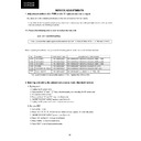
REF NO
DESCRIPTION
PART NUMBER
PRICE CODE
New
edge
mounting
points
including 4 self tapping screws
and 2 threaded screws.
and 2 threaded screws.
CSAKAA009WJ02
AA
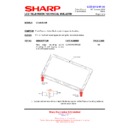
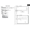
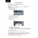
1. Locate and remove with a sharp knife the top section of the Fascia mounting points as
can be seen above.
LCD 2012 01 06
Date of Issue:
30
th
January 2012
Classification:
White
LCD TELEVISION TECHNICAL BULLETIN
Page 2 of 3
Sharp Electronics (UK) Limited
Reference – LCEU229
Revision - 1
White – Carry out as required
Yellow – Carry out as required and whenever the unit comes in for service
Red – Carry out on all units
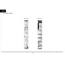
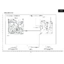
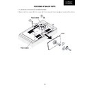
2. Slide the 2 metal plates supplied over the ends of the lower metal mounting chassis plate
and place a small piece of tape as shown below to hold them in place.
Position of tape to retain during assembly.
LCD 2012 01 06
Date of Issue:
30
th
January 2012
Classification:
White
LCD TELEVISION TECHNICAL BULLETIN
Page 3 of 3
Sharp Electronics (UK) Limited
Reference – LCEU229
Revision - 1
White – Carry out as required
Yellow – Carry out as required and whenever the unit comes in for service
Red – Carry out on all units
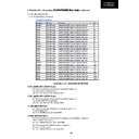
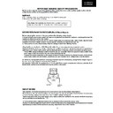
3. Using the supplied plastic screws add 2 to each corner to secure chassis to Fascia.
4. Refit back and use the 2 Threaded screws to retain lower back corners.

